Front OCP module and XCC management module cable routing
Follow instructions in this section to install and route the cable for the front OCP module and XCC management module.
Note
- Depending on the specific configuration, the information in this topic might not apply to your node.
Connections between connectors; 1↔1, 2↔2, 3↔3, ... n↔n
When routing the cables, make sure that all cables are routed appropriately through the corresponding cable guides and cable clips.
Figure 1. OCP cable and front I/O cable in the front OCP configuration

| From (Front OCP cage) | To (system board) | Cable | |
|---|---|---|---|
| 1 Front OCP cage (secured with screws) | 1a OCP signal connector | GenZ 4C+ OCP connector | to MCIO x16 (225 mm) |
| 1b OCP power and sideband connector | to MCIO x8 (445 mm) | ||
| 2 Front I/O signal connector | 2 Front I/O signal connector | SlimSAS x4 to low-profile SlimSAS x8 (155 mm) | |
Note
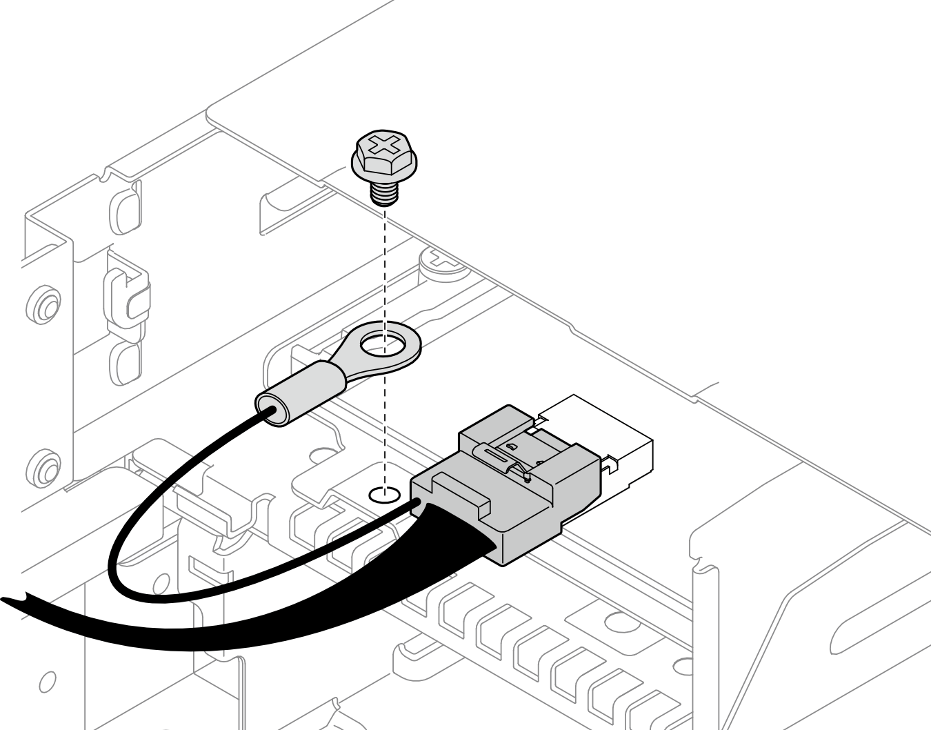
When connecting the front I/O cable to the front OCP cage, make sure to secure the attached grounding cable with a screw.
Figure 2. Screw of the front I/O grounding cable
Important
Between 1 and 1a: the OCP cable must be separated from the DIMMs by the lower partitions of the front air baffle.
Between 1a and 1b: When processor 2 is installed, the rear part of the longer OCP cable must be separated from the DIMMs either by the lower partitions of the rear air baffle or by the cable ducts under the 2U performance PHM.
Give documentation feedback