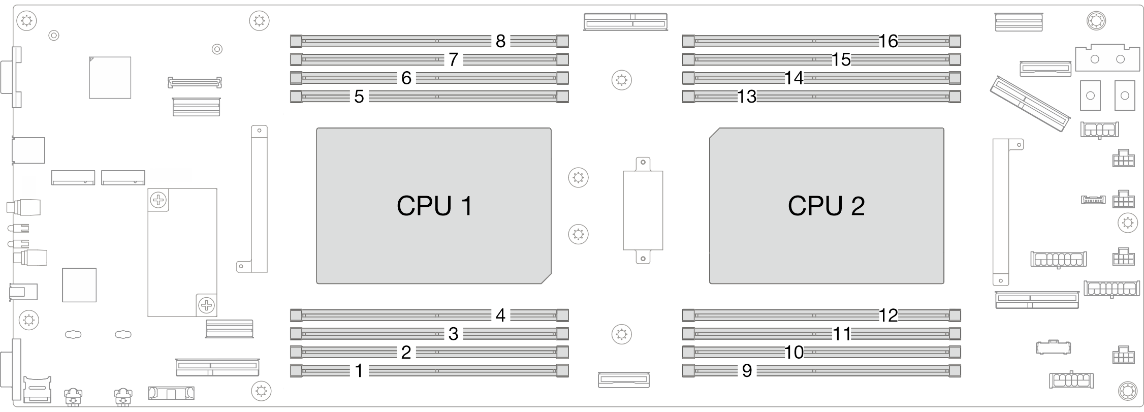
Memory module installation rules and order
Memory modules must be installed in a specific order based on the memory configuration that you implement and the number of processors and memory modules installed in the server.
Supported memory types
For information on the types of memory module supported by this server, see Memory section in Technical Specifications.
Information about optimizing memory performance and configuring memory is available at the Lenovo Press website:
In addition, you can take advantage of a memory configurator, which is available at the following site:
Lenovo Enterprise Solutions Configurator (Memory Configurations)
For the specific information about the required installation order of memory modules in SD550 V3 based on the system configuration and memory mode that you are implementing, see below.
Memory modules and processors layout

The memory-channel configuration table below shows the relationship between the processors, memory controllers, memory channels, and memory module slot numbers.
| Processor | Processor 1 | ||||||||
|---|---|---|---|---|---|---|---|---|---|
| Channel | CH1 (7/H) | CH0 (6/G) | CH1 (5/F) | CH0 (4/E) | CH0 (0/A) | CH1 (1/B) | CH0 (2/C) | CH1 (3/D) | |
| DIMM slot No. | 8 | 7 | 6 | 5 | 4 | 3 | 2 | 1 | |
| Processor | Processor 2 | ||||||||
| Channel | CH1 (3/D) | CH0 (2/C) | CH1 (1/B) | CH0 (0/A) | CH0 (4/E) | CH1 (5/F) | CH0 (6/G) | CH1 (7/H) | |
| DIMM slot No. | 16 | 15 | 14 | 13 | 12 | 11 | 10 | 9 | |
Memory module installation guideline
- The following memory configurations and population sequences are supported on ThinkSystem SD550 V3:
DRAM DIMMs installation order (RDIMMs or 3DS RDIMMs)
At least one DIMM is required for each processor. Install at least eight DIMMs per processor for good performance.
When a DIMM is replaced, the node provides automatic DIMM enablement capability without requiring you to use the Setup Utility to enable the new DIMM manually.
- Install DIMMs of the same speed for optimal performance. Otherwise, the BIOS will find and run the lowest speed among all channels.
- Within a channel, always populate DIMMs with the maximum number of ranks in the farthest DIMM slot, followed by the nearest DIMM slot.
- When a processor is installed, each of the DIMM slots connected to the processor must be installed with a DIMM or DIMM filler.
- DIMM slots 1-8 are connected to processor 1
- DIMM slots 9-16 are connected to processor 2