Memory mirroring mode: Installation guidelines and sequence
Memory module installation order for memory mirroring with two processors installed in a compute node.
The following illustration shows the location of the DIMM connectors on the system board.
Figure 1. The location of the DIMM connectors on the system board
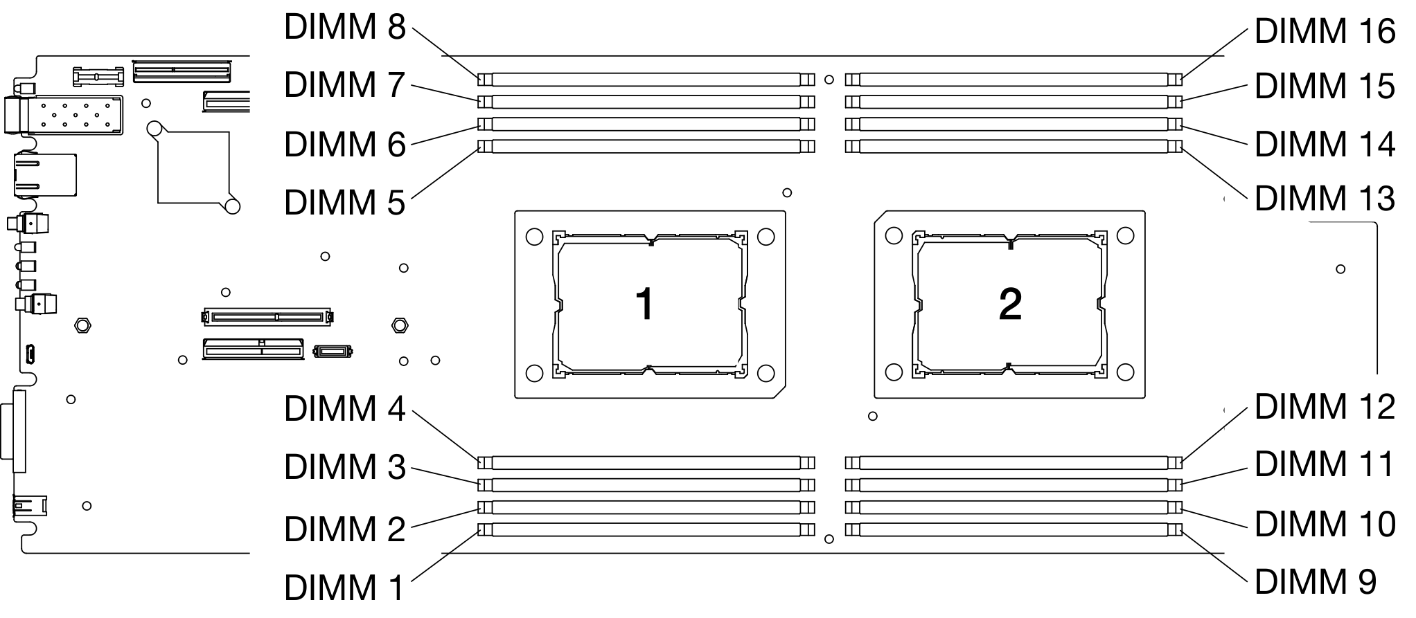
See the following table for memory channels and DIMM slots information around a processor.
| Integrated Memory Controller (iMC) | Controller 0 | Controller 1 | Controller 2 | Controller 3 | ||||
| Channel | Channel 0 | Channel 1 | Channel 0 | Channel 1 | Channel 0 | Channel 1 | Channel 0 | Channel 1 |
| DIMM connector (Processor 1) | 2 | 1 | 4 | 3 | 7 | 8 | 5 | 6 |
| DIMM connector (Processor 2) | 15 | 16 | 13 | 14 | 10 | 9 | 12 | 11 |
Memory mirroring mode — DIMM installation guidelines
- Memory mirroring can be configured across memory channel 0 and memory channel 1.
- The total memory capacity of memory channel 0 must equal to that of memory channel 1.
- Populate both memory channel 0 and memory channel 1 of each memory controller.
- For the memory-mirroring mode, ThinkSystem SD630 V2 Compute Node only supports the memory configuration with 16 DIMMs. Populate all of the DIMM slots with DIMMs that are identical in capacity and architecture.
Memory mirroring mode — DIMM population sequence
Note
When adding one or more DIMMs during a memory upgrade, you might need to remove some DIMMs that are already installed to new locations.
| Total | Processor 1 | Processor 2 | Total | |||||||||||||||
|---|---|---|---|---|---|---|---|---|---|---|---|---|---|---|---|---|---|---|
| DIMMs | 1 | 2 | 3 | 4 | 5 | 6 | 7 | 8 | 9 | 10 | 11 | 12 | 13 | 14 | 15 | 16 | DIMMs | |
| 161 | 1 | 2 | 3 | 4 | 5 | 6 | 7 | 8 | 9 | 10 | 11 | 12 | 13 | 14 | 15 | 16 | 16 | |
Note
DIMM configurations that support Sub NUMA Clustering (SNC), which can be enabled via UEFI.
Give documentation feedback