Independent memory mode: Installation guidelines and sequence
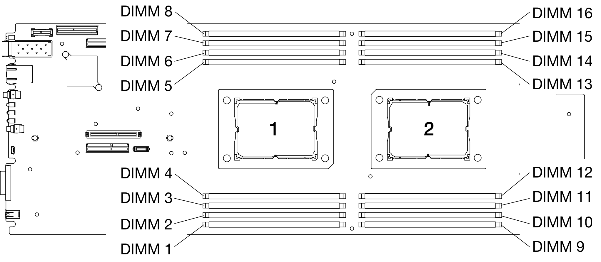
Memory module installation order for independent memory mode with two processors installed in a compute node.
| Integrated Memory Controller (iMC) | Controller 0 | Controller 1 | Controller 2 | Controller 3 | ||||
| Channel | Channel 0 | Channel 1 | Channel 0 | Channel 1 | Channel 0 | Channel 1 | Channel 0 | Channel 1 |
| DIMM connector (Processor 1) | 2 | 1 | 4 | 3 | 7 | 8 | 5 | 6 |
| DIMM connector (Processor 2) | 15 | 16 | 13 | 14 | 10 | 9 | 12 | 11 |
Independent memory mode — DIMM installation guidelines
- Install the DIMMs for processor 1 before working on processor 2. Balance the DIMMs across the two processors so that all processors have the same memory capacity.
- Populate memory controller 0 first for each processor. Balance the DIMMs across the processor memory controllers so all of the memory controllers have exactly the same DIMM population and memory capacity.
- DA240 Enclosure and ThinkSystem SD630 V2 supports up to two types of memory capacity.
- Of all the memory controllers, make sure that memory channel 0 and memory channel 1 are configured with the same total memory capacity respectively. It is required to install DIMMs with the same capacity for memory channel 0 . However, the total memory capacity of memory channel 0 is allowed to be different from that of memory channel 1.
- A maximum of eight logical ranks per memory channel are allowed.
- Populate all memory channels for optimal performance. For memory configurations that do not require or allow use of all memory channels, all memory channels that are populated should have the same number of DIMMs, the same total memory capacity, and the same total number of memory ranks.
- Memory configurations with DIMM quantities of 4, 8, 12, and 16 are supported.
- Installing an equal number of DIMMs for each processor is recommended. A minimum of two DDR4 DIMM is required for each processor.
Independent memory mode — DIMM population sequence
For the independent mode, install the DIMMs (of the same capacity) in the following order: 2, 15, 4, 13, 7, 10, 5, 12, 1, 16, 8, 9, 3, 14, 6, 11
When adding one or more DIMMs during a memory upgrade, you might need to remove some DIMMs that are already installed to new locations.
| Total | Processor 1 | Processor 2 | Total | |||||||||||||||
|---|---|---|---|---|---|---|---|---|---|---|---|---|---|---|---|---|---|---|
| DIMMs | 1 | 2 | 3 | 4 | 5 | 6 | 7 | 8 | 9 | 10 | 11 | 12 | 13 | 14 | 15 | 16 | DIMMs | |
| 41 | 2 | 4 | 13 | 15 | 41 | |||||||||||||
| 42 | 2 | 3 | 14 | 15 | 42 | |||||||||||||
| 81 & 3 | 2 | 4 | 5 | 7 | 10 | 12 | 13 | 15 | 81 | |||||||||
| 82 | 2 | 3 | 6 | 7 | 10 | 11 | 14 | 15 | 82 | |||||||||
| 121 | 1 | 2 | 4 | 5 | 7 | 8 | 9 | 10 | 12 | 13 | 15 | 16 | 121 | |||||
| 163 & 4 | 1 | 2 | 3 | 4 | 5 | 6 | 7 | 8 | 9 | 10 | 11 | 12 | 13 | 14 | 15 | 16 | 16 | |
Follow this population sequence if all of the DIMMs have the same memory capacity.
Follow this population sequence if the DIMMs in memory channel 0 have a different memory capacity from those in memory channel 1.
DIMM configurations that support Sub NUMA Clustering (SNC), which can be enabled via UEFI.
DIMM configurations that support Software Guard Extensions (SGX), see Enable Software Guard Extensions (SGX) to enable this feature.