System-board switches
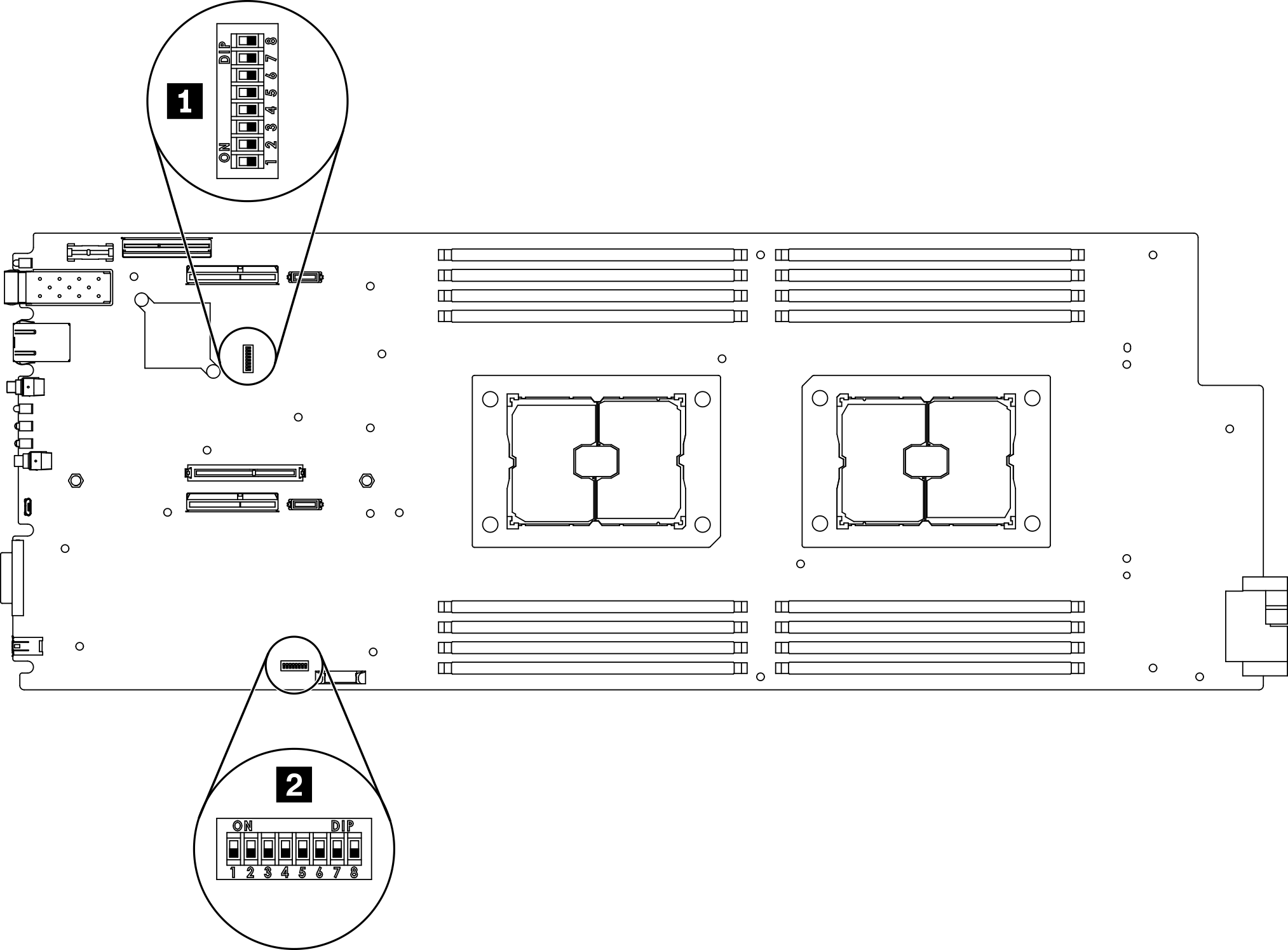
The following illustration shows the location and description of the switches.
Important
- If there is a clear protective sticker on the switch blocks, you must remove and discard it to access the switches.
- Any system-board switch or jumper block that is not shown in the illustrations in this document are reserved.
Figure 1. Location of the switches on the system board
The following table describes the switches on the system board:
| Switch block | Switch | Switch name | Usage description | |
|---|---|---|---|---|
| Open | Close | |||
| 1 SW2 | 4 | Password override jumper | Overrides the power-on password | Normal (default) |
| 7 | Lenovo XClarity Controller force update | Enables Lenovo XClarity Controller force update | Normal (default) | |
| 2 SW3 | 3 | CMOS clear jumper | Clears the real-time clock (RTC) registry | Normal (default) |
Important
- Before you change any switch settings or move any jumpers, turn off the solution. Then, disconnect all power cords and external cables. Review the information in Safety Information page, Installation Guidelines, and Power off the compute node.
- Any system-board switches or jumper blocks that are not shown in the illustrations in this document are reserved.
Give documentation feedback