System-board connectors
The following illustrations show the internal connectors on the system board.
Figure 1. Internal connectors on compute node system board
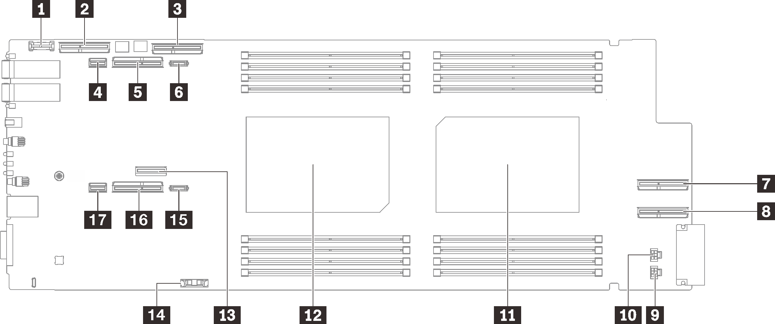
| 1 Trusted cryptographic module (TCM) connector | 10 Drive power 2 connector |
| 2 PCIe x 16 MCIO 1 connector | 11 Processor 2 connector |
| 3 PCIe x 16 MCIO 2 connector | 12 Processor 1 connector |
| 4 SATA 0-1 connector | 13 M.2 connector |
| 5 PCIe x16 Gen 5 slot for PCIe riser 2 or NVMe 0-1 connector | 14 CMOS battery (CR2032) connector |
| 6 PCIe 2 power connector | 15 PCIe 1 power connector |
| 7 PCIe x 16 MCIO 3 connector | 16 PCIe x16 Gen 5 slot for PCIe riser 1 or NVMe 2-3 connector |
| 8 PCIe x 16 MCIO 4 connector | 17 SATA 2-3 connector |
| 9 Drive power 1 connector |
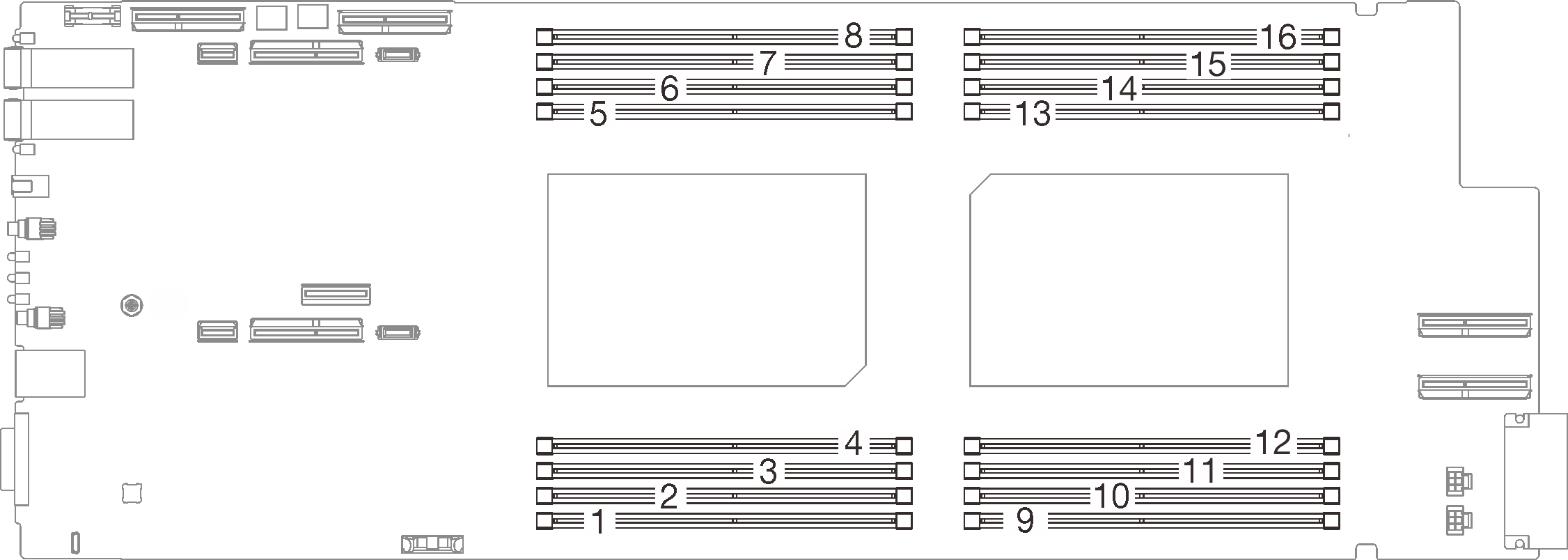
The following illustration shows the location of the DIMM slots numbering on the system board of the compute node.
Figure 2. DIMM slots numbering on compute node system board
Give documentation feedback