Front LEDs and buttons
The following illustration shows LEDs and buttons on the front of the solution. By viewing the status of LEDs, you can often identify the source of the error.
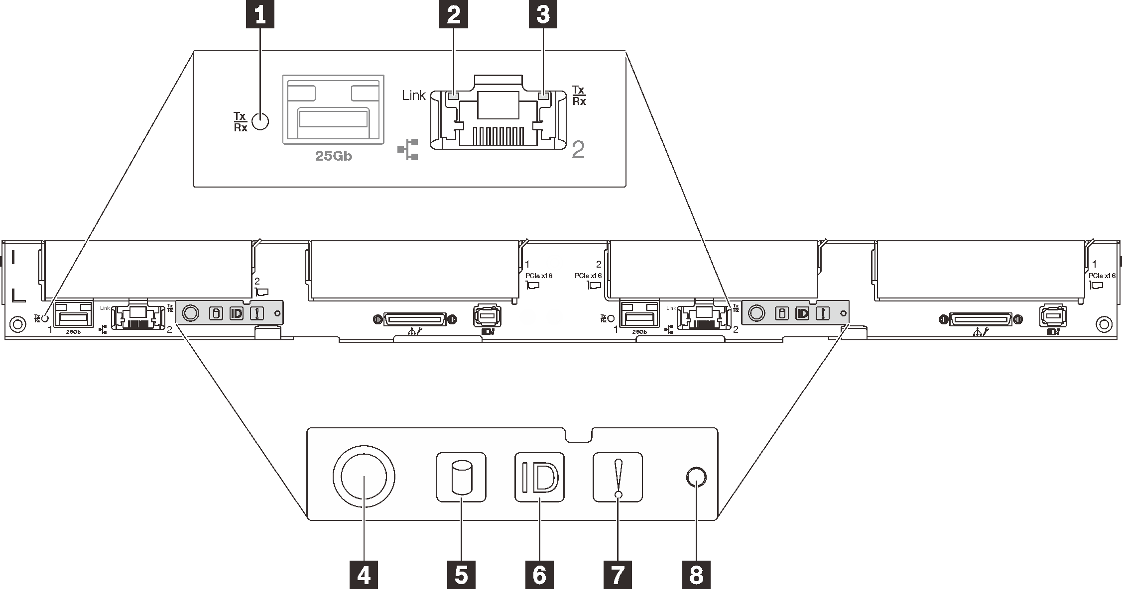
| 1 25 Gb Ethernet port link and activity (SFP28) LED (green) | 5 Drive activity LED (green) |
| 2 1 Gb Ethernet port link (RJ45) LED (green) | 6 Identification LED (blue) |
| 3 1 Gb Ethernet port activity (RJ45) LED (green) | 7 System-error LED (yellow) |
| 4 Node power button / LED (green) | 8 NMI button |
1 25 Gb Ethernet port link and activity (SFP28) LED (green): Use this green LED to distinguish the network status.
- Off: The network is disconnected.
- Blinking: The network is accessing.
- On: The network is established.
2 1 Gb Ethernet port link (RJ45) LED (green): Use this green LED to distinguish the network status.
- Off: The network link is disconnected.
- On: The network link is established.
3 1 Gb Ethernet port activity (RJ45) LED (green): Use this green LED to distinguish the network status.
- Off: The node is disconnected from a LAN.
- Blinking: The network is connected and active.
- Off: Power is not present or the power supply, or the LED itself has failed.
- Flashing rapidly (4 times per second): The node is turned off and is not ready to be turned on. The power button is disabled. This will last approximately 5 to 10 seconds.
- Flashing slowly (once per second): The node is turned off and is ready to be turned on. You can press the power button to turn on the node.
- On: The node is turned on.
5 Drive activity LED (green): If the LED is lit, it indicates that the drive is powered, but not actively reading or writing data. If the LED is flashing, the drive is being accessed.
6 Identification LED (blue): Use this blue LED to visually locate the node among other nodes. You can light this LED remotely with Lenovo XClarity Administrator.
7 System-error LED (yellow): When this yellow LED is lit, it indicates that a system error has occurred.
8 NMI button: Press this button to force a nonmaskable interrupt to the processor. You might have to use a pen or the end of a straightened paper clip to press the button. You can also use it to force a blue-screen memory dump (use this button only when you are directed to do so by Lenovo Support).