Front view
The following illustration shows the controls, LEDs, and connectors on the front of the solution.
Enclosure
Note
The illustrations in this document might differ slightly from your hardware.
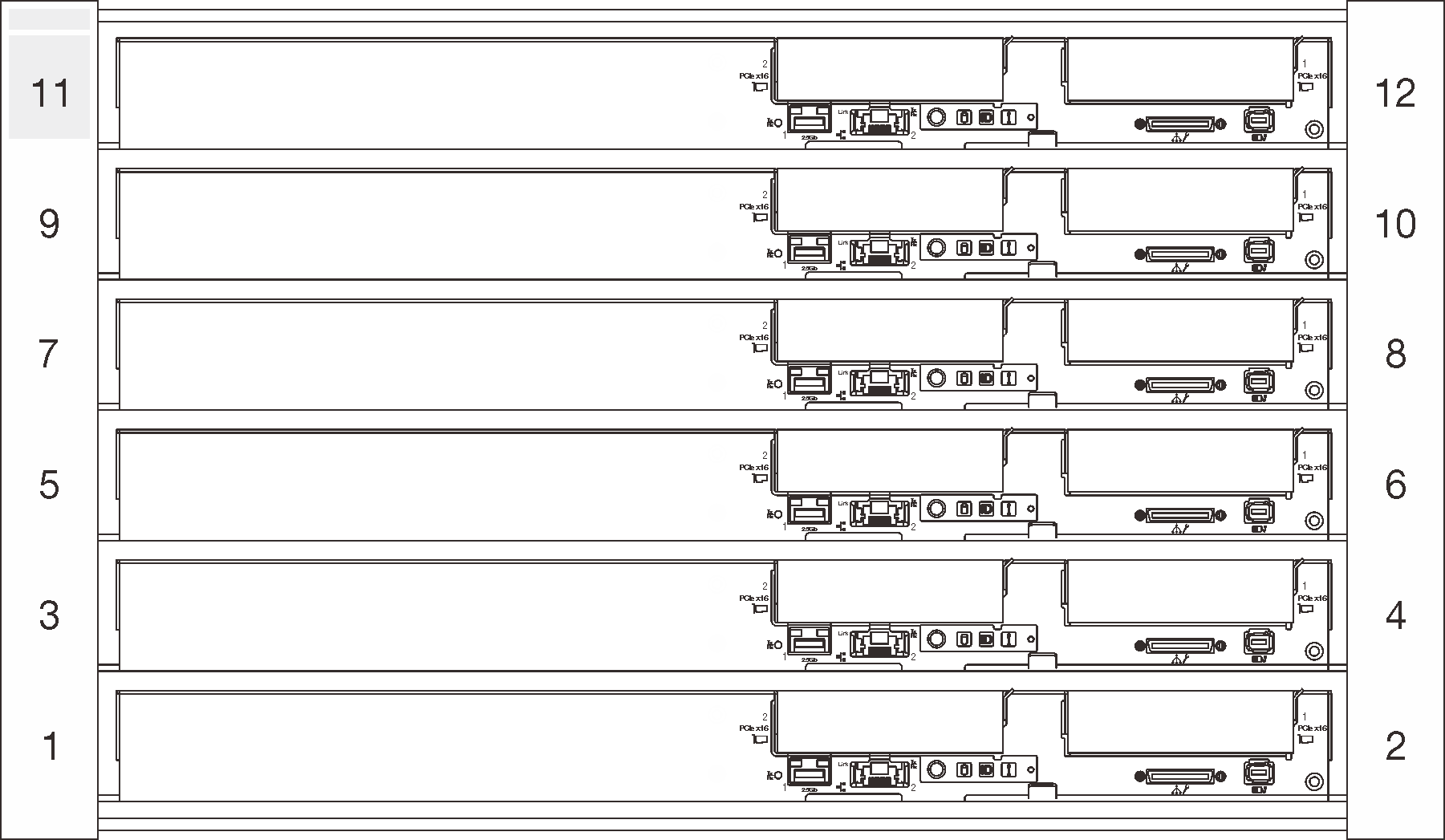
The enclosure supports up to six trays.
The following illustration shows six trays installed in the enclosure.
The slot numbers are indicated on both sides of the enclosure.
Figure 1. Enclosure with six SD650 V2 trays
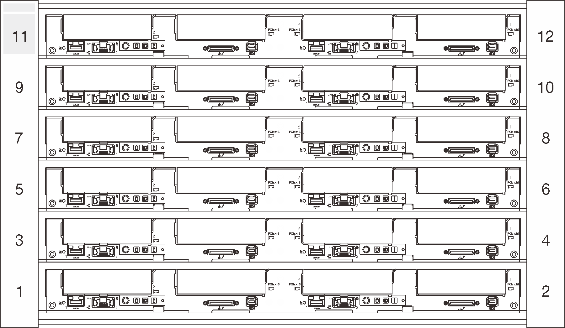
Figure 2. Enclosure with six SD650-N V2 trays
SD650 V2 tray
The following illustrations show the controls, LEDs, and connectors on the front of each tray.
Figure 3. SD650 V2 tray
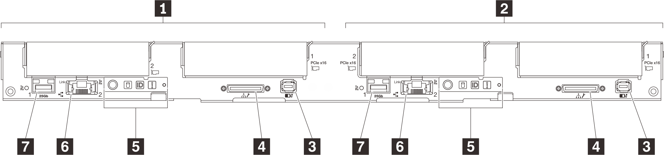
| 1 Left node (odd bay numbers) | 5 Front operator panel |
| 2 Right node (even bay numbers) | 6 1 Gb RJ45 Ethernet port with share-NIC feature for Lenovo XClarity Controller |
| 3 External LCD diagnostics handset connector | 7 25 Gb SFP28 Ethernet port with share-NIC feature for Lenovo XClarity Controller |
| 4 USB 3.0 Console Breakout Cable |
SD650-N V2 tray
The following illustrations show the controls, LEDs, and connectors on the front of each tray.
Figure 4. SD650-N V2 tray
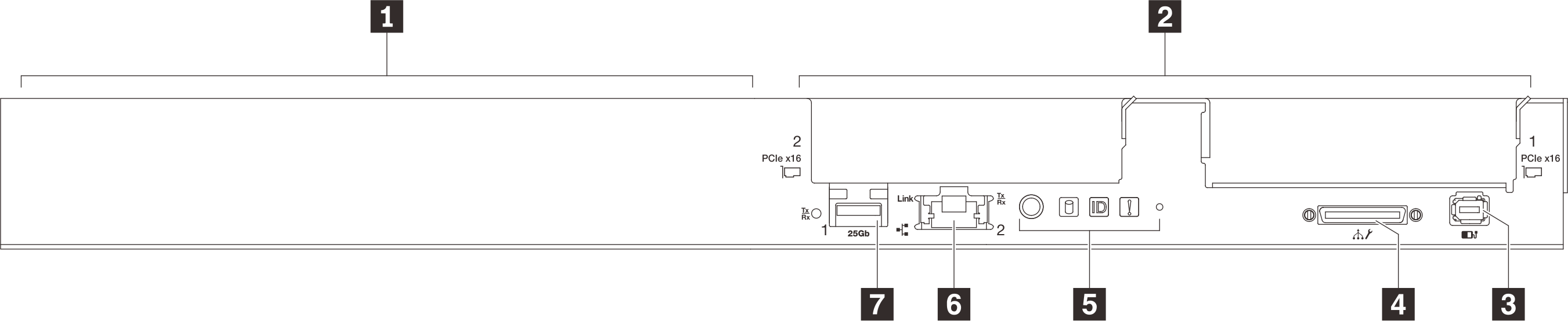
| 1 GPU node/Left node (odd bay numbers) | 5 Front operator panel |
| 2 Compute node/Right node (even bay numbers) | 6 1 Gb RJ45 Ethernet port with share-NIC feature for Lenovo XClarity Controller |
| 3 External LCD diagnostics handset connector | 7 25 Gb SFP28 Ethernet port with share-NIC feature for Lenovo XClarity Controller |
| 4 USB 3.0 Console Breakout Cable |
Give documentation feedback