Install the enclosure midplane
(Trained service technician only) Use this information to install the enclosure midplane.
About this task

- Read the following sections to ensure that you work safely.
Procedure
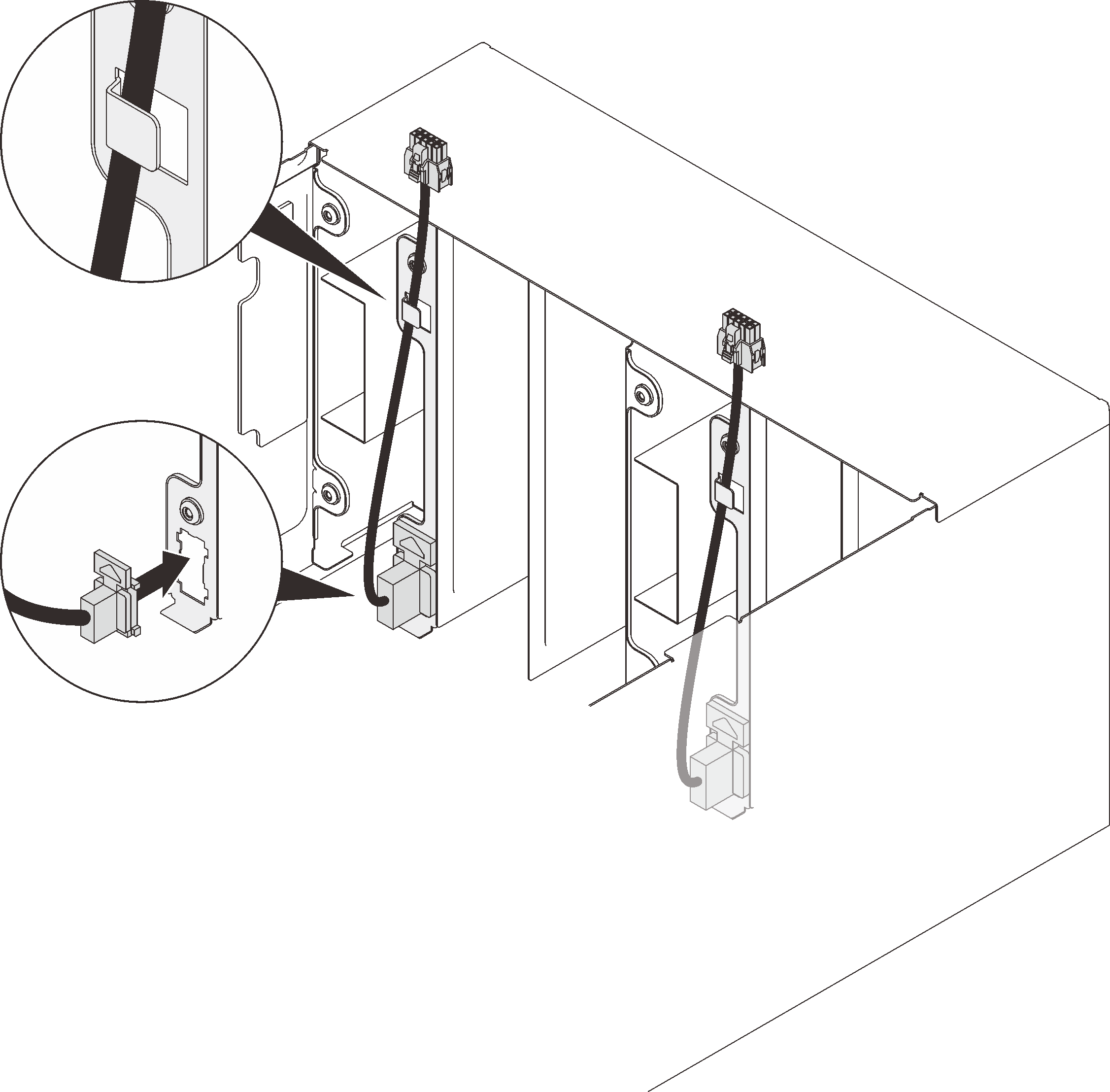
- Connect the two fan cables to the enclosure and route the cables through cable clips.Figure 1. Fan cable installation
- Install the midplane.
- ❸ Connect the fan cables to the midplane.Figure 2. Enclosure midplane installation
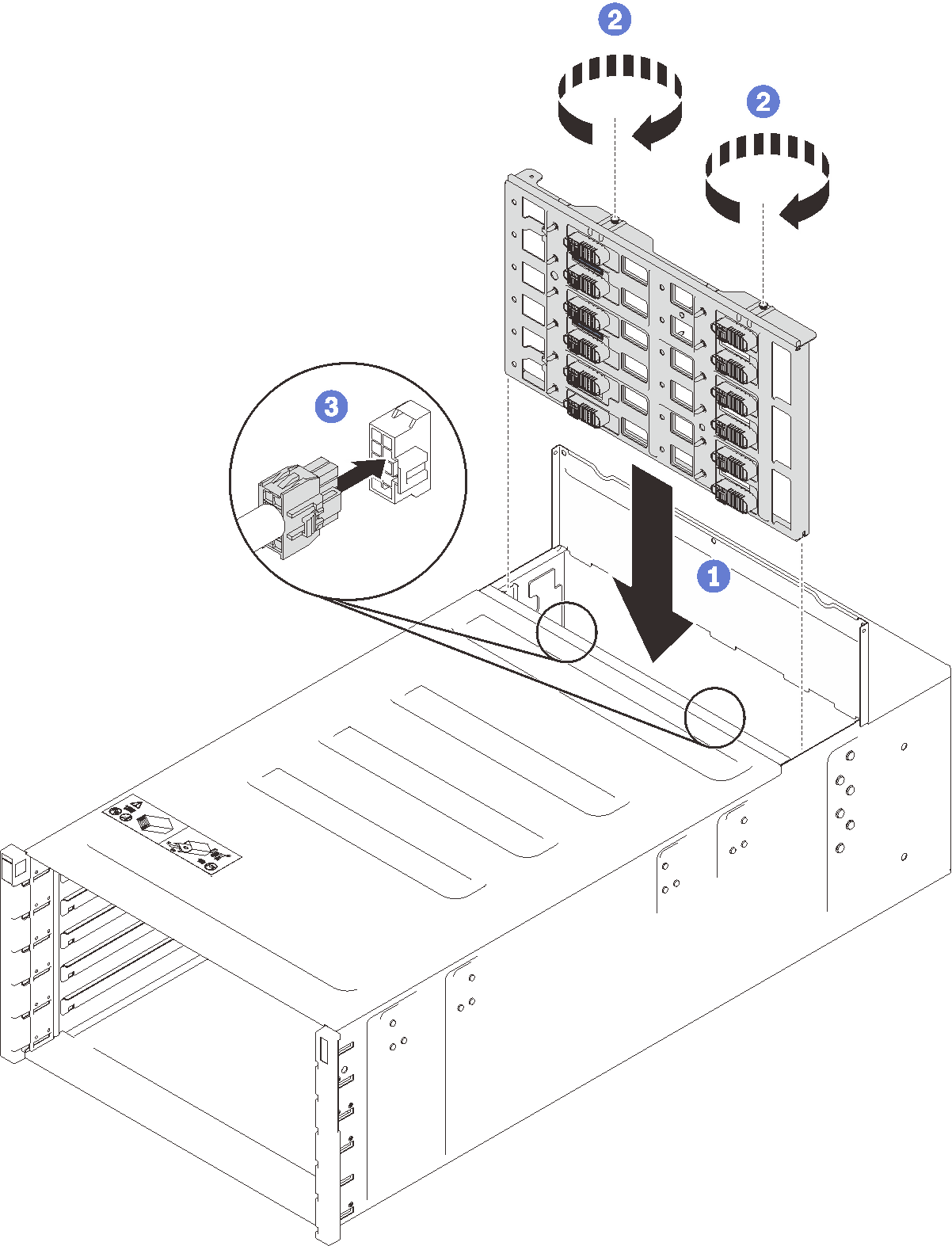
- ❸ Connect the fan cables to the midplane.
- Install the top cover.
- ❷ Tighten the three captive screws on the top cover.Figure 3. Top cover inward rotation
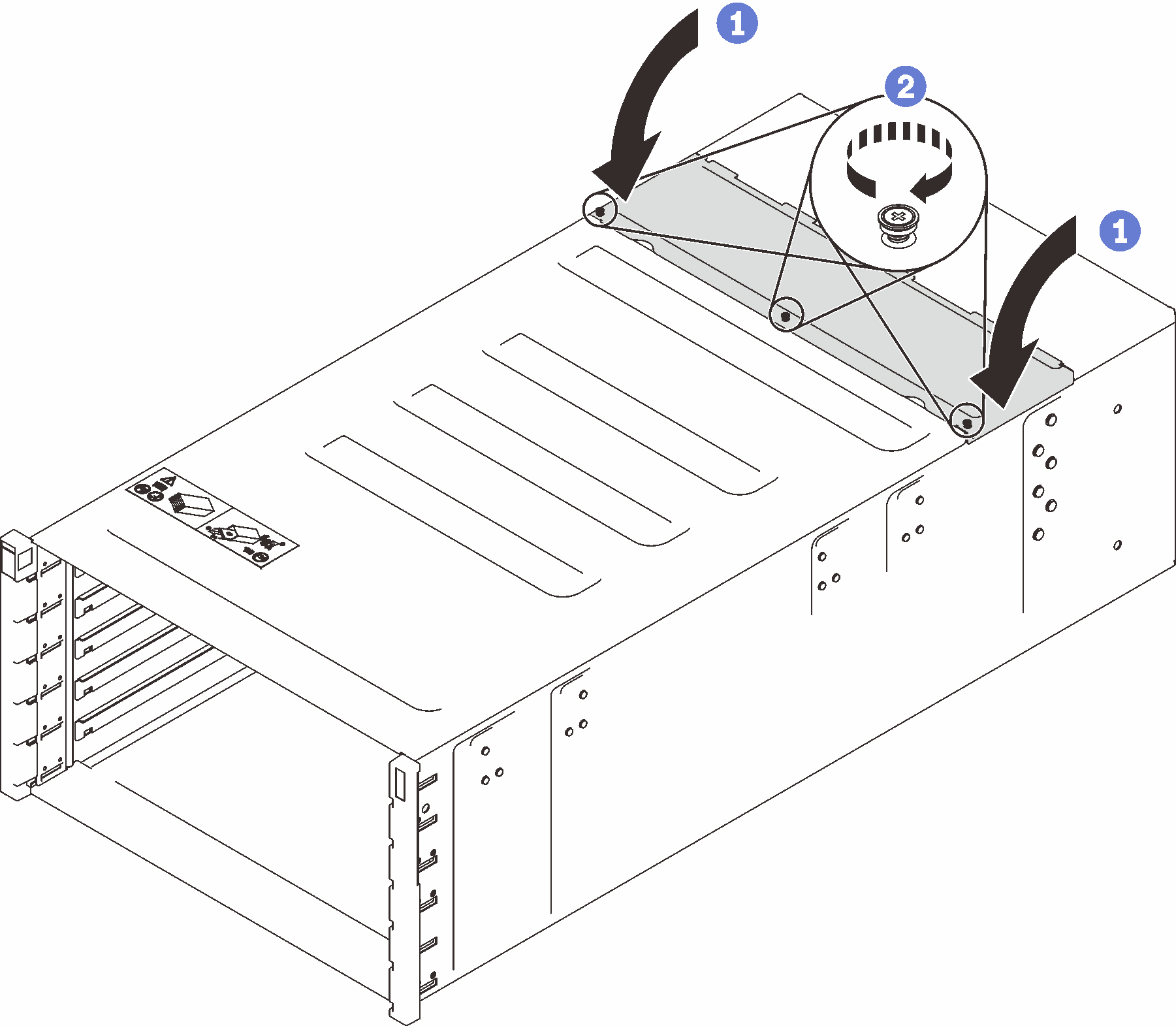
- ❷ Tighten the three captive screws on the top cover.
After you finish
Reassemble the enclosure and program the vital product data (VPD) that is stored on the card. Complete the following steps:
Two technicians must hold the front and rear handles at both sides of the enclosure.
One technician must protect the cables from damage.
Carefully put the enclosure into the rack and slide the enclosure until rear handles are near front rack rails; then, remove rear handles at both sides.
Figure 4. Rear handle removal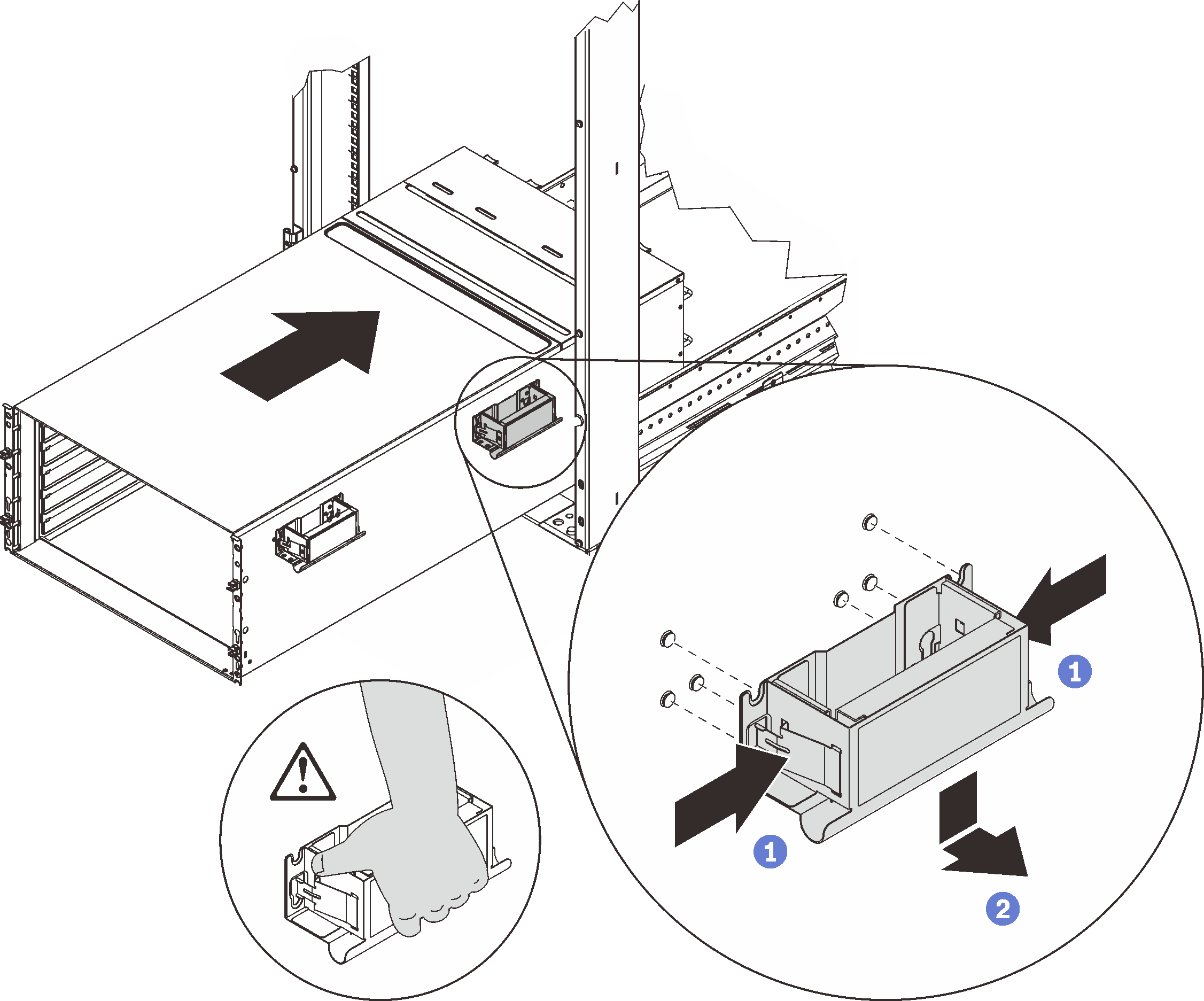
Slide the enclosure farther into the rack until front handles are near front rack rails; then, remove front handles at both sides.
Figure 5. Front handle removal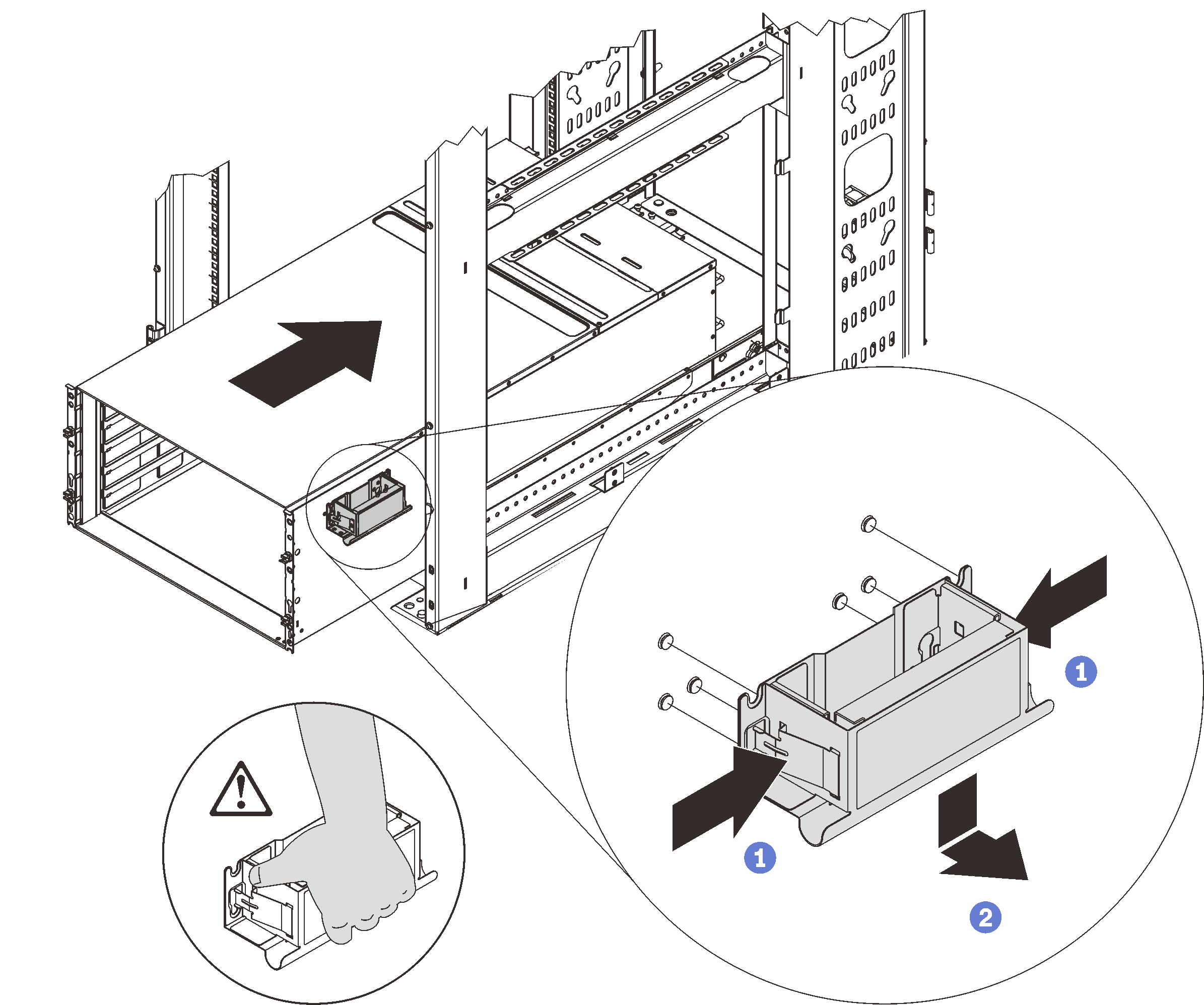
Side the enclosure all the way back to the rack.
Figure 6. Sliding the rack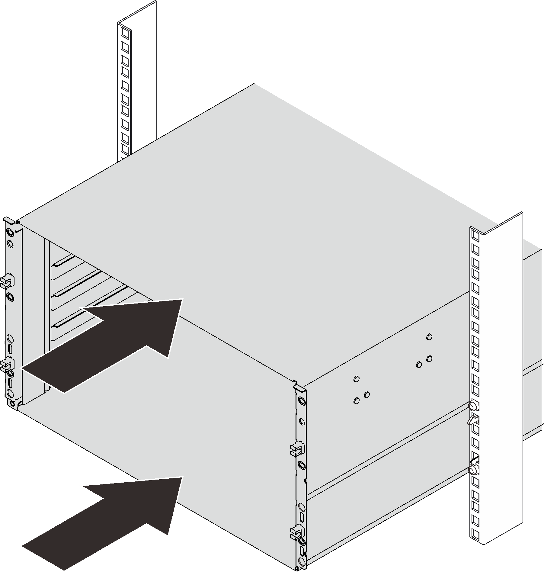
Secure the enclosure to the rack with six screws; then, reinstall the EIA covers.
Figure 7. EIA cover installation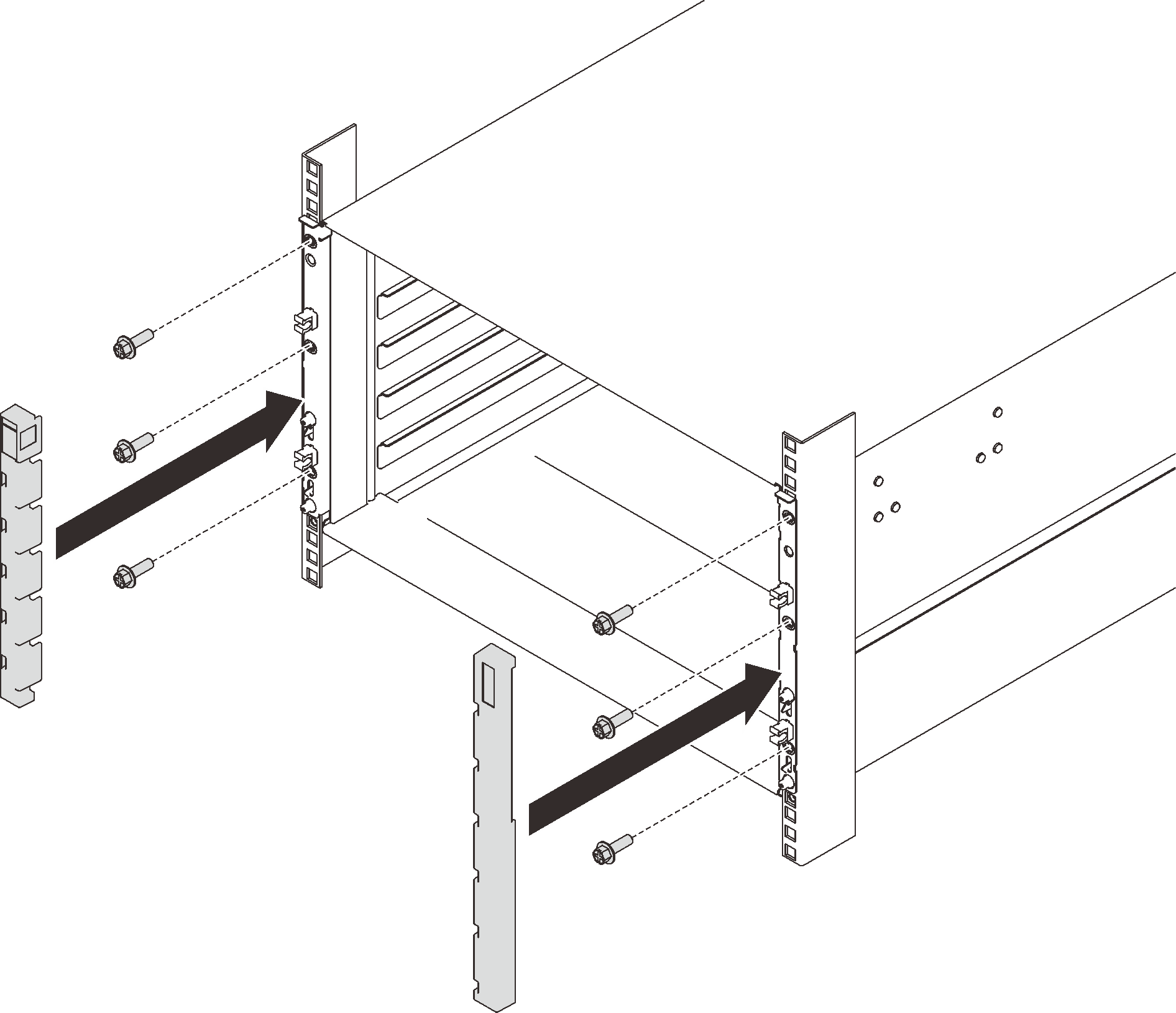
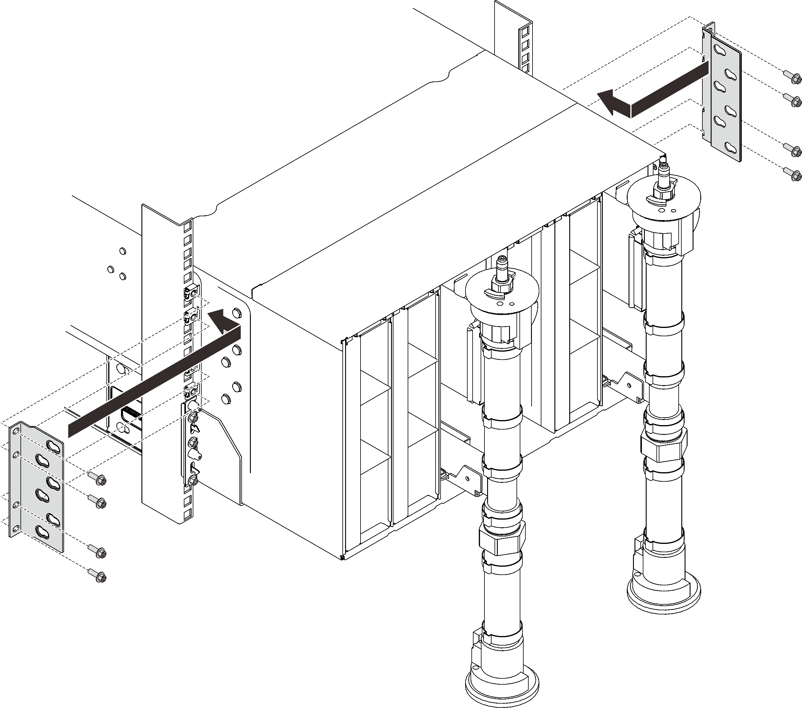
- Reinstall eight screws to secure two support brackets on the rear enclosure.Figure 8. Support bracket installation
Reinstall eight screws (using the screwdriver contained in the manifold repair kit) to secure two manifolds.
Figure 9. Manifold screw locations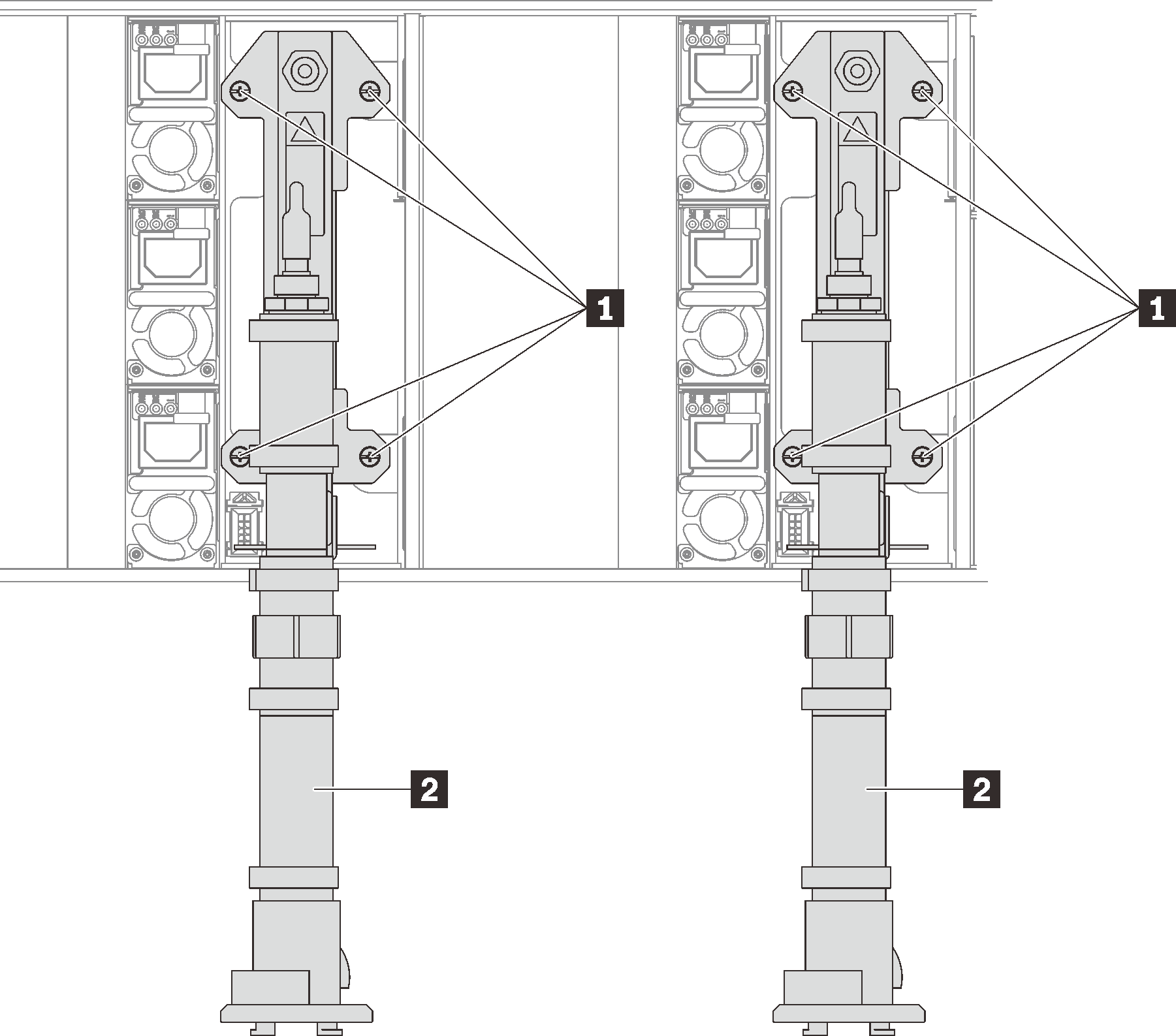
Table 1. Manifold screw locations 1 Screws 2 Manifold Reinstall all power supplies back to the enclosure.
Figure 10. Power supply installation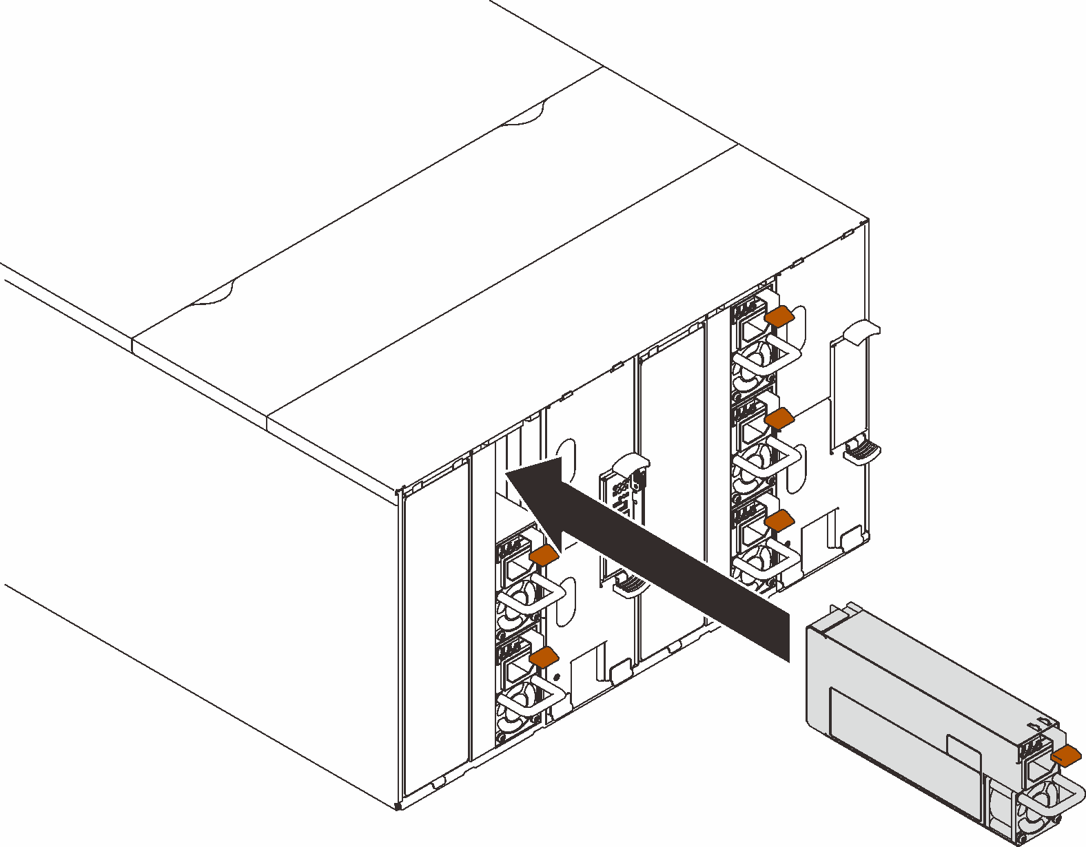
- Reinstall the blank filler.Figure 11. Blank filler installation
Reinstall the SMM2 support bracket and the SMM2.
Figure 12. SMM2 support bracket installation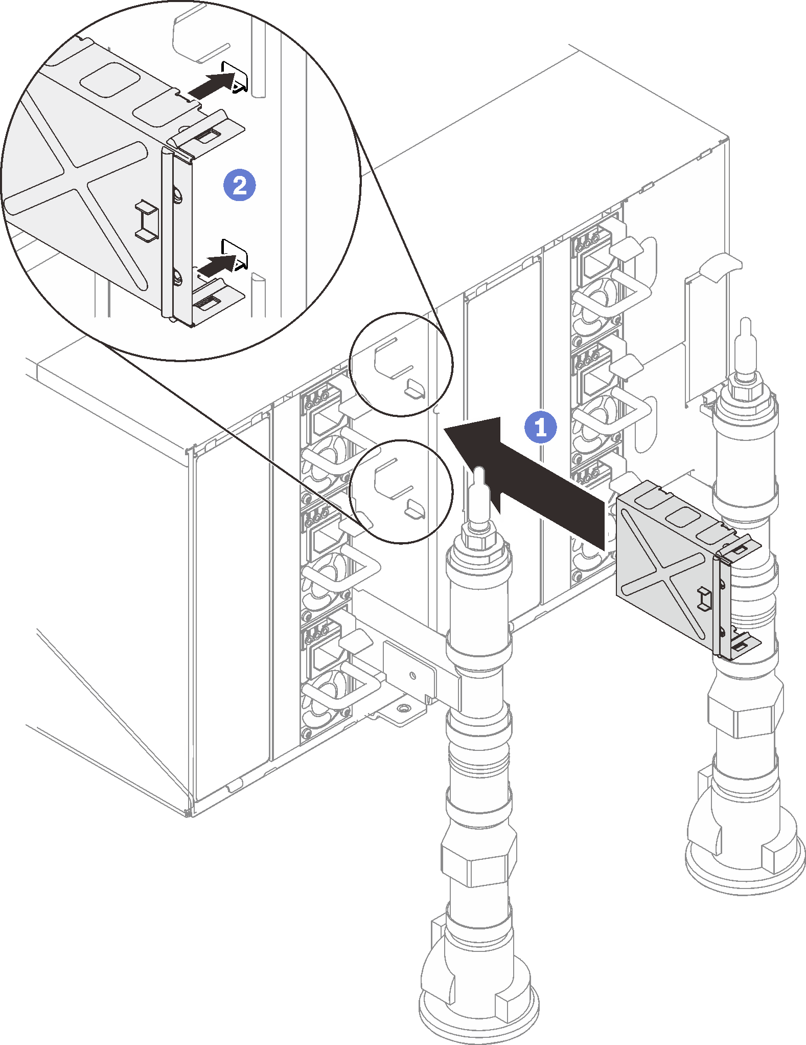 Figure 13. SMM2 installation
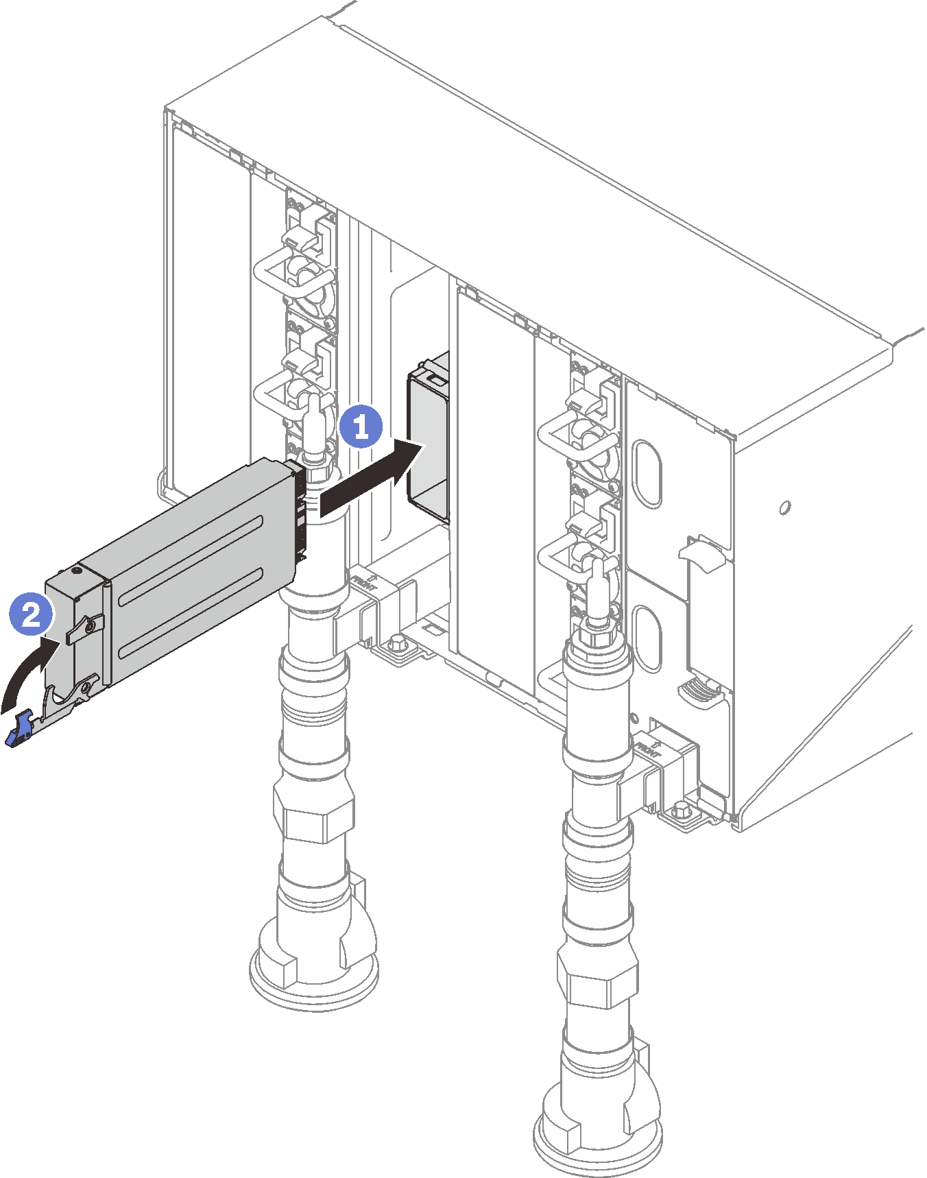
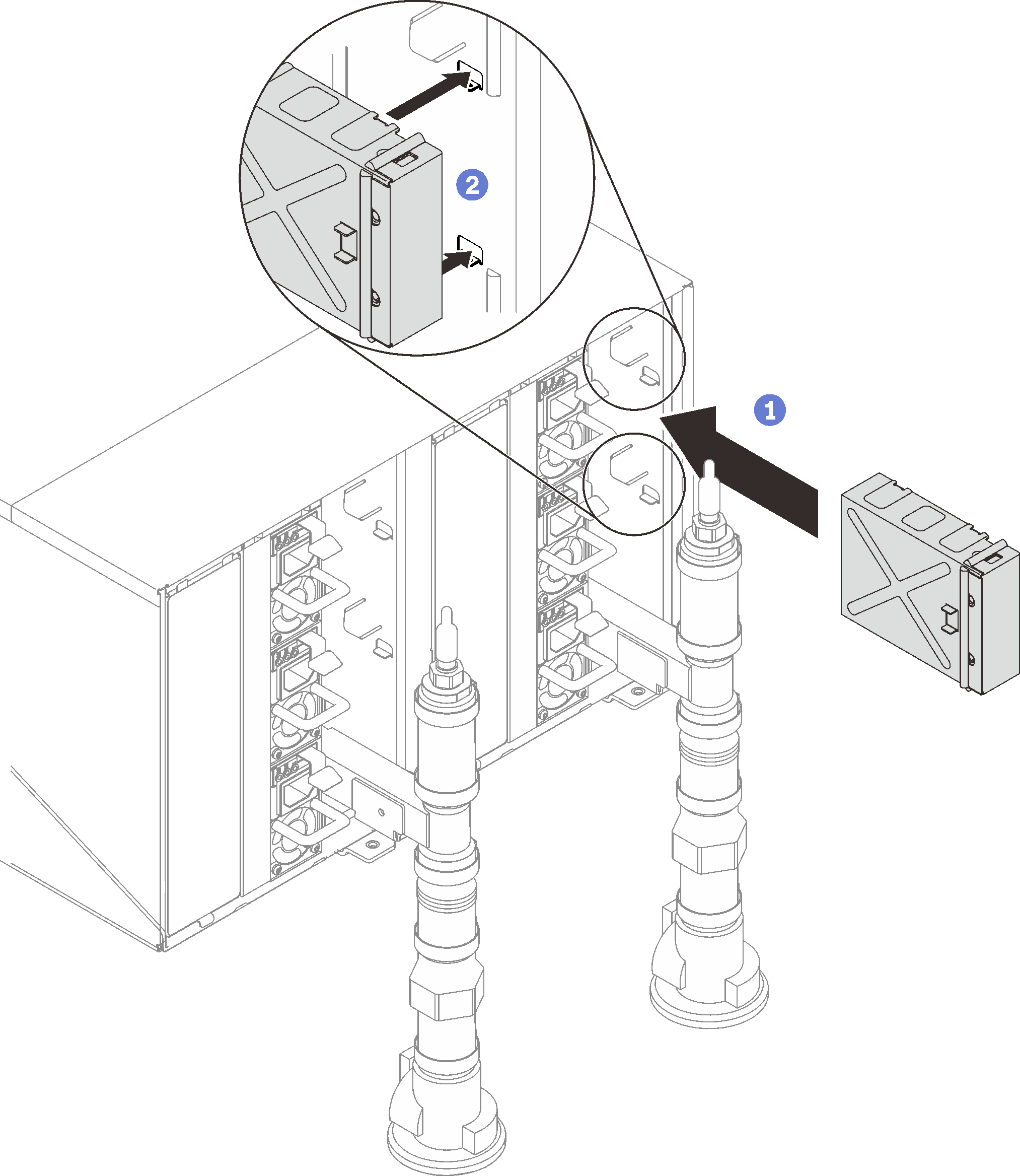
Reinstall manifold retention brackets that are retaining the manifolds (top enclosure position only).
Figure 14. Retention bracket installation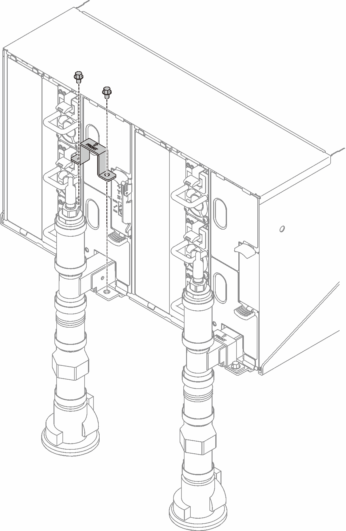
Align the drip sensor assembly with the enclosure and slide it into place.
Figure 15. Drip sensor assembly installation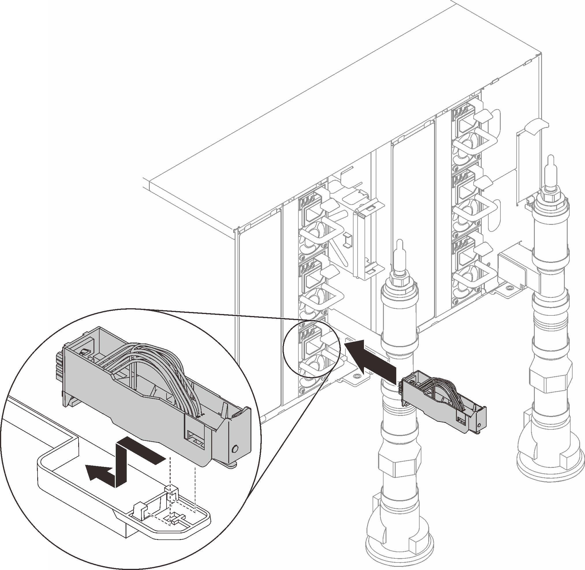
Reinstall all EMC shields.
Figure 16. EMC shields installation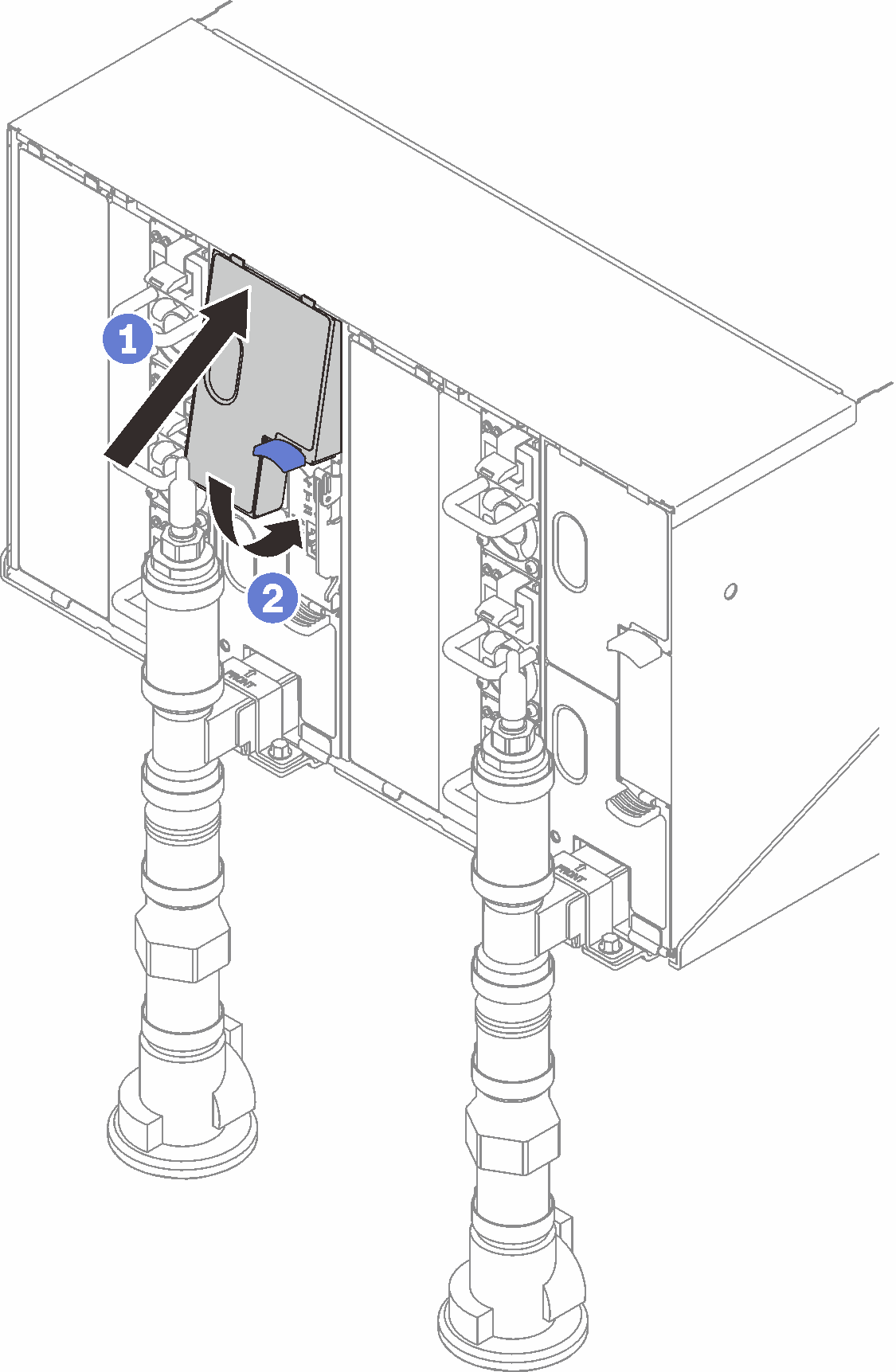 Figure 17. EMC shields installation
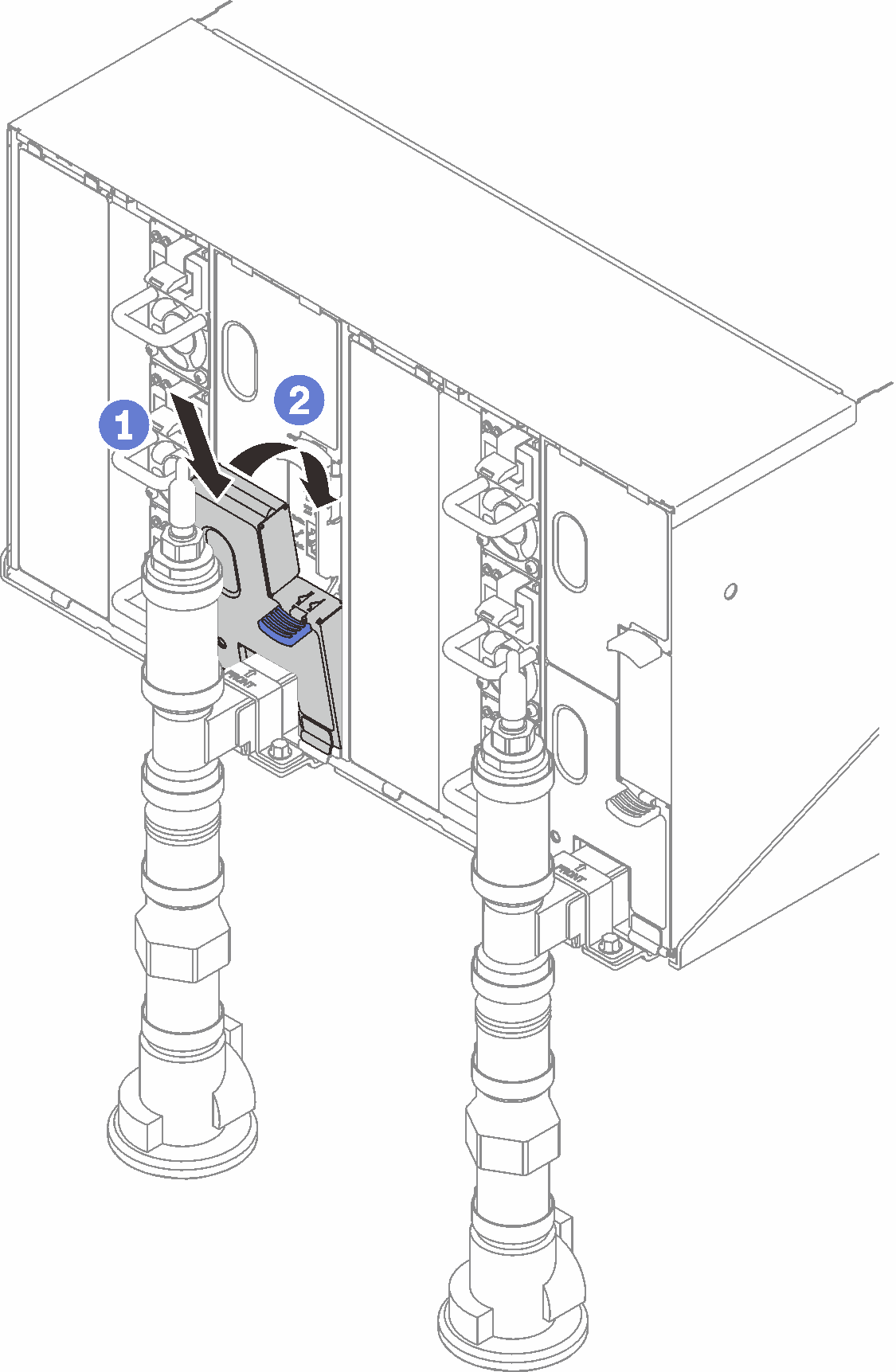
- Reinstall the components that you removed from the rear of the enclosure.
- Connect any cables that you disconnected from the modules in the rear of the enclosure.
- Connect the enclosure to power.
- Write down new enclosure midplane serial number (for example: Y030UN34B063) and UUID (for example: 2E2B686CC6B311E2907C6EAE8B16A49E).
- Update the solution firmware to the latest level.
- Log in to the web interface.
- Go to System Information section, click on the Midplane VPD tab.
- Update the new enclosure midplane serial number and UUID onto the fan and power controller.
- Close the release handles on the tray in order to seat the nodes in the enclosure midplane connectors.
- Restart any nodes that you shut down. See the documentation that comes with the compute node for detailed instructions.
- The fan and power controller is powered-on automatically.
Demo video