Water leak problems
Use this information to resolve issues related to water leaks.
Suspicious leakage symptoms
Processor over temperature error indicated by the System Error "!" LED being solid ON at the front of the node
One or more of the nodes shut down unexpectedly
- Enclosure SMM2 management may report the following events:
18040179 : DripSensor 1 Out: Chassis, Predictive Failure asserted was asserted.
1804017A : DripSensor 2 Out: Chassis, Predictive Failure asserted was asserted.
18080076 : DripSensor 1: Chassis, Device Removed / Device Absent was asserted.
18080077 : DripSensor 2: Chassis, Device Removed / Device Absent was asserted.
Leak at quick connects during installation or removal procedures
Leak in the water loop tubing
Check enclosure SMM2 messages to see if any leakage warnings have been reported. See Messages and Codes Reference for more information.
Walk to the rear of the rack and visually check the status of each enclosure's left and right side drip sensor LEDs.
Users usually have multiple enclosures per rack. Each enclosure has two drip sensors.NoteEach enclosure has two drip sensors that should turn on a yellow LED visible through a hole located in the lower left leg of the lower EMC shield if the sensor detects moisture in its drip sensor catch basin.Figure 1. Drip sensor LED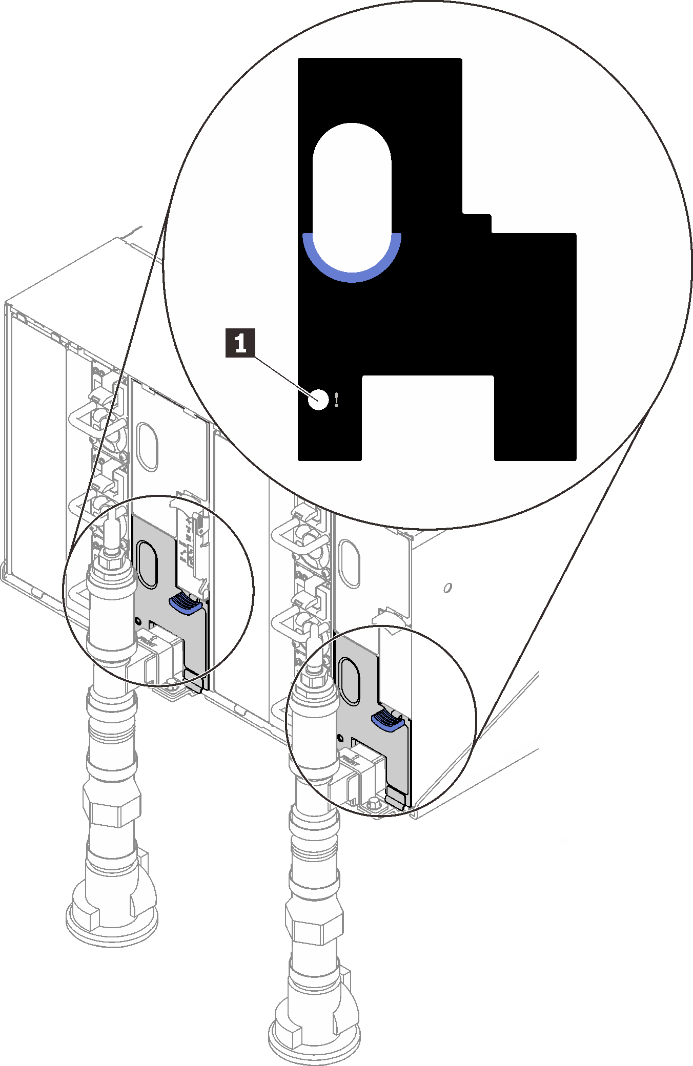
Table 1. Drip sensor LED 1 Drip sensor LED (yellow) Visually check the drip sensor catch basin for any moisture.
Remove the lower left EMC shield in the front of the left drip sensor.
Figure 2. Lower left EMC shield removal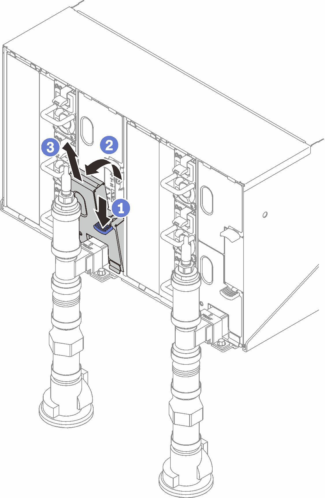 NoteIf there is a manifold vertical pipe in front of the EMC shield, you need to slide it sideways out from underneath the pipe.
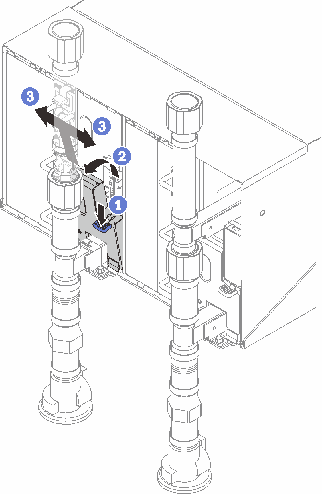
Use a flashlight to visually inspect the plastic catch basin for any moisture.
Re-install the EMC shield.
Figure 3. Lower left EMC shield installation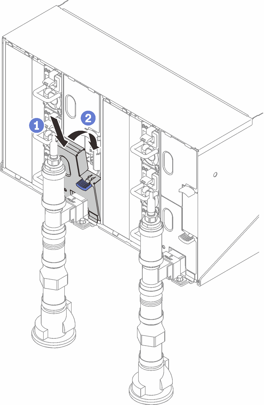
Repeat steps for the right side drip sensor catch basin.
Power down all nodes either through the OS or by pressing and holding the power button for five seconds.
NoteGreen Power LED for each node (two per compute tray) should be blinking to indicate the nodes are in standby state.Disconnect power cords from all six enclosure power supplies.
ImportantFully disconnect the power to the entire enclosure prior to attempting to identify a leak within an enclosure.Check the water loop for any moisture.
Remove the top node (bays 11&12) from the enclosure (see Remove a DWC tray from the enclosure), place it on a stable work surface, remove the cover (see Remove the tray cover), and carefully inspect the entire water loop (both rubber and copper tubing) for any signs of moisture. Re-install the compute tray into enclosure (see Install a DWC tray in the enclosure).
Repeat steps for the tray in bays 9 and 10.
Repeat steps for the tray in bays 7 and 8.
Repeat steps for the tray in bays 5 and 6.
Repeat steps for the tray in bays 3 and 4.
Repeat steps for the tray in bays 1 and 2.
NoteIt is important to visually inspect the bottom of the enclosure with a flashlight prior to re-installing the bottom most tray (bays 1 and 2) into the enclosure.
If you are unable to identify the problem in the steps above, then you may need to replace one or more of the tray water loops (see Water loop (SD650 V2 tray) replacement). Contact Product Engineer for the further assistance.