Install a drive cage assembly
Use this information to install a drive cage assembly.
About this task
Attention
Read Installation Guidelines and Safety inspection checklist to ensure that you work safely.
Ensure the drives are installed correctly into the drive cage assembly. See Install a drive.
Note
Ensure you have
SD650-I V3 Neptune DWC Waterloop Service Kit
in hand to install components.
Watch the procedure
- A video of this procedure is available at YouTube.
Procedure
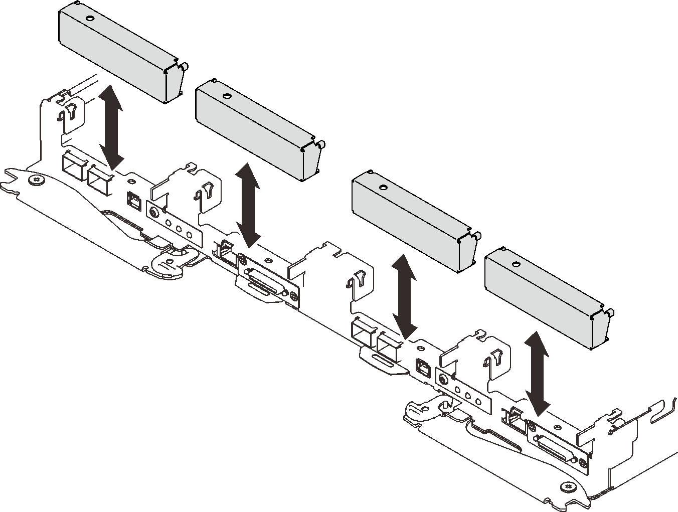
- Make sure the blank bezel fillers are installed. If not, install them to the node.Figure 1. Blank bezel filler installation
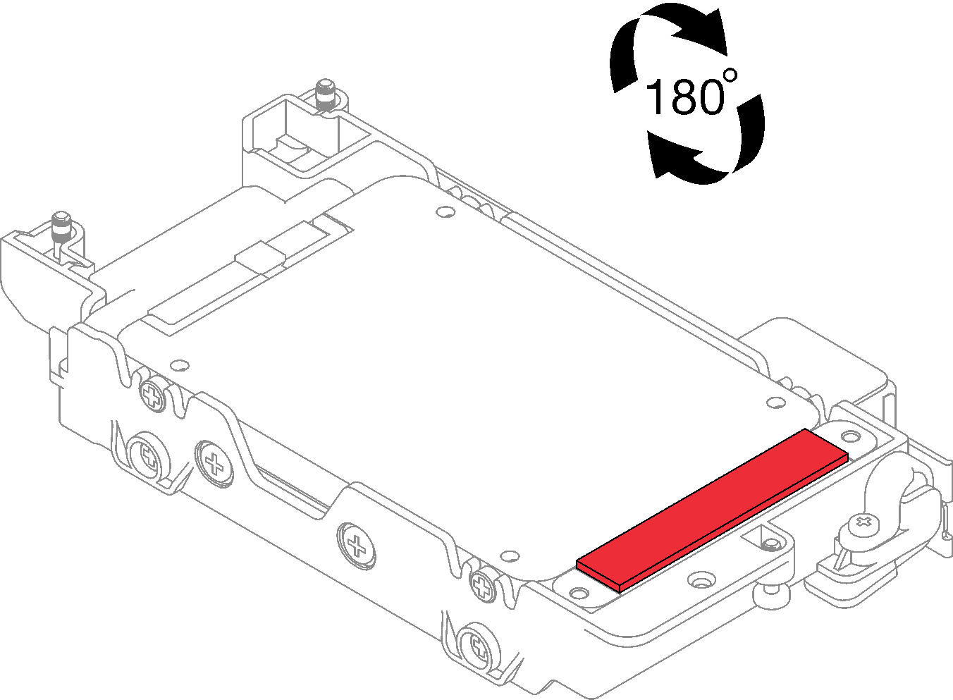
- If the gap pad located on the reverse side of the drive cage is damaged or detached, replace it with a new one. Make sure to follow Gap pad/putty pad replacement guidelines.Figure 2. Gap pad location
- If the drive cage gap pad is damaged or detached, replace it with a new one. See the following for the gap pad location for each drive cage. Make sure to follow Gap pad/putty pad replacement guidelines.NoteAlign the gap pad with marking on water loop when attaching gap pad.Figure 3. Markings on water loop for gap pad alignment
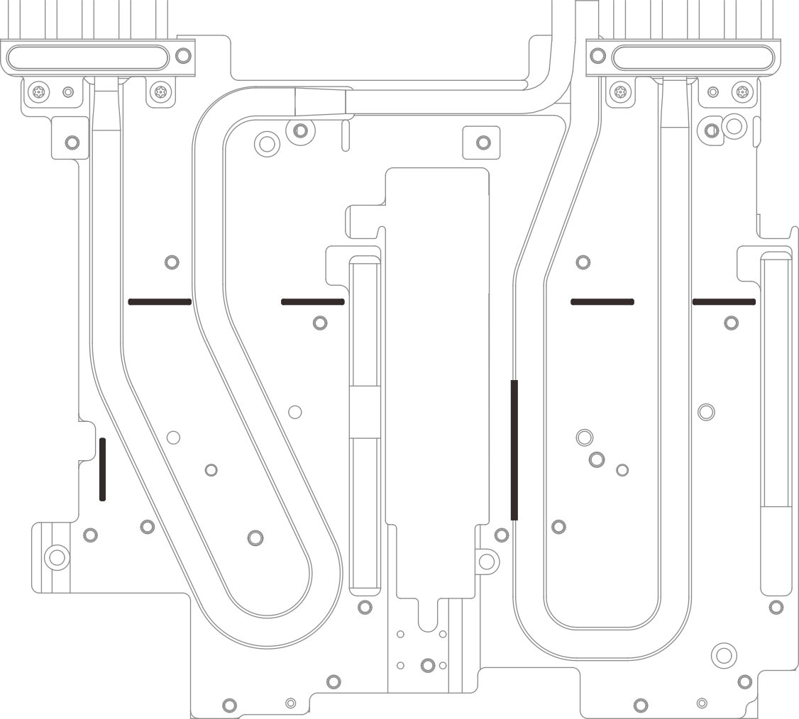 Figure 4. Replacing gap pad
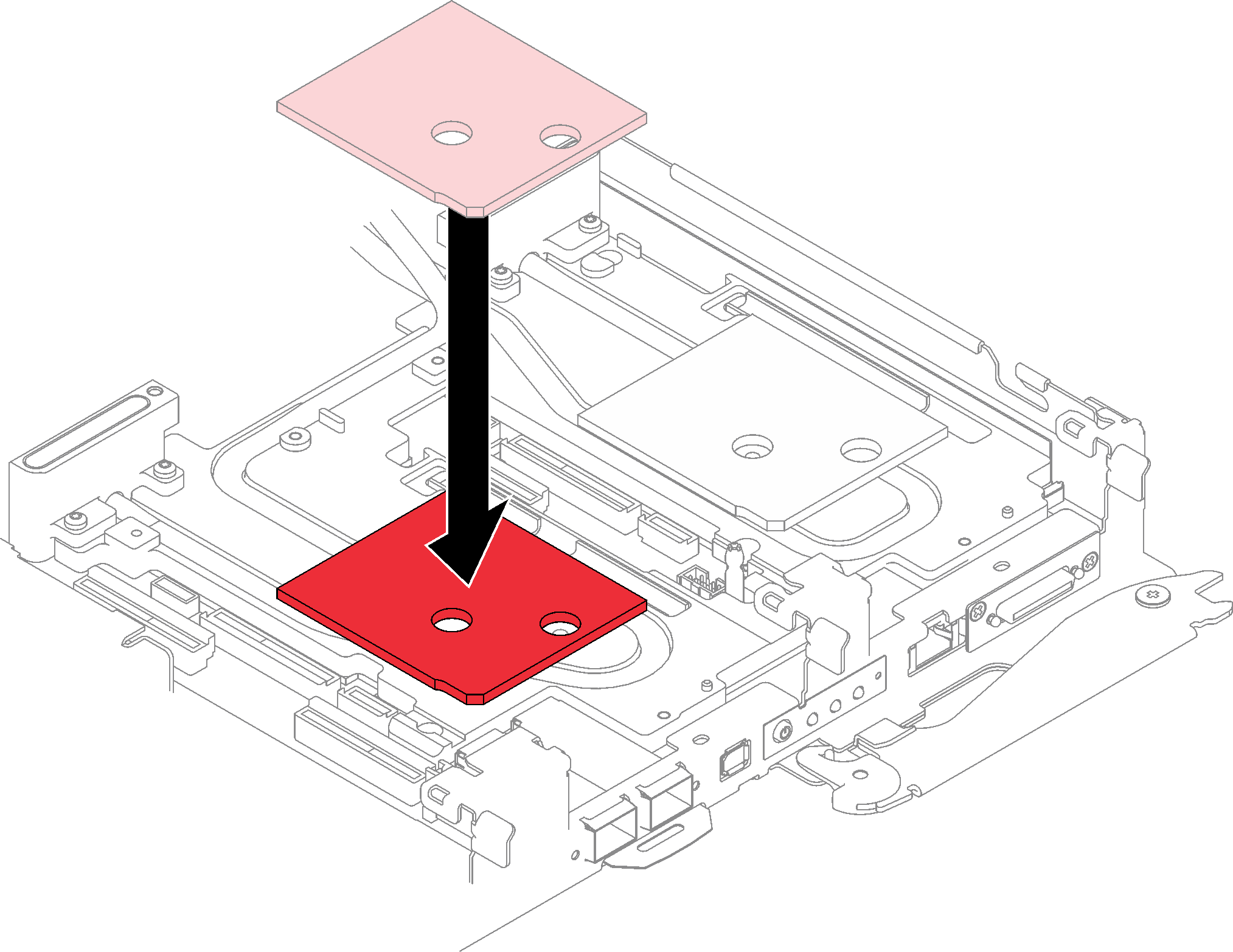 Figure 5. Gap pad locations
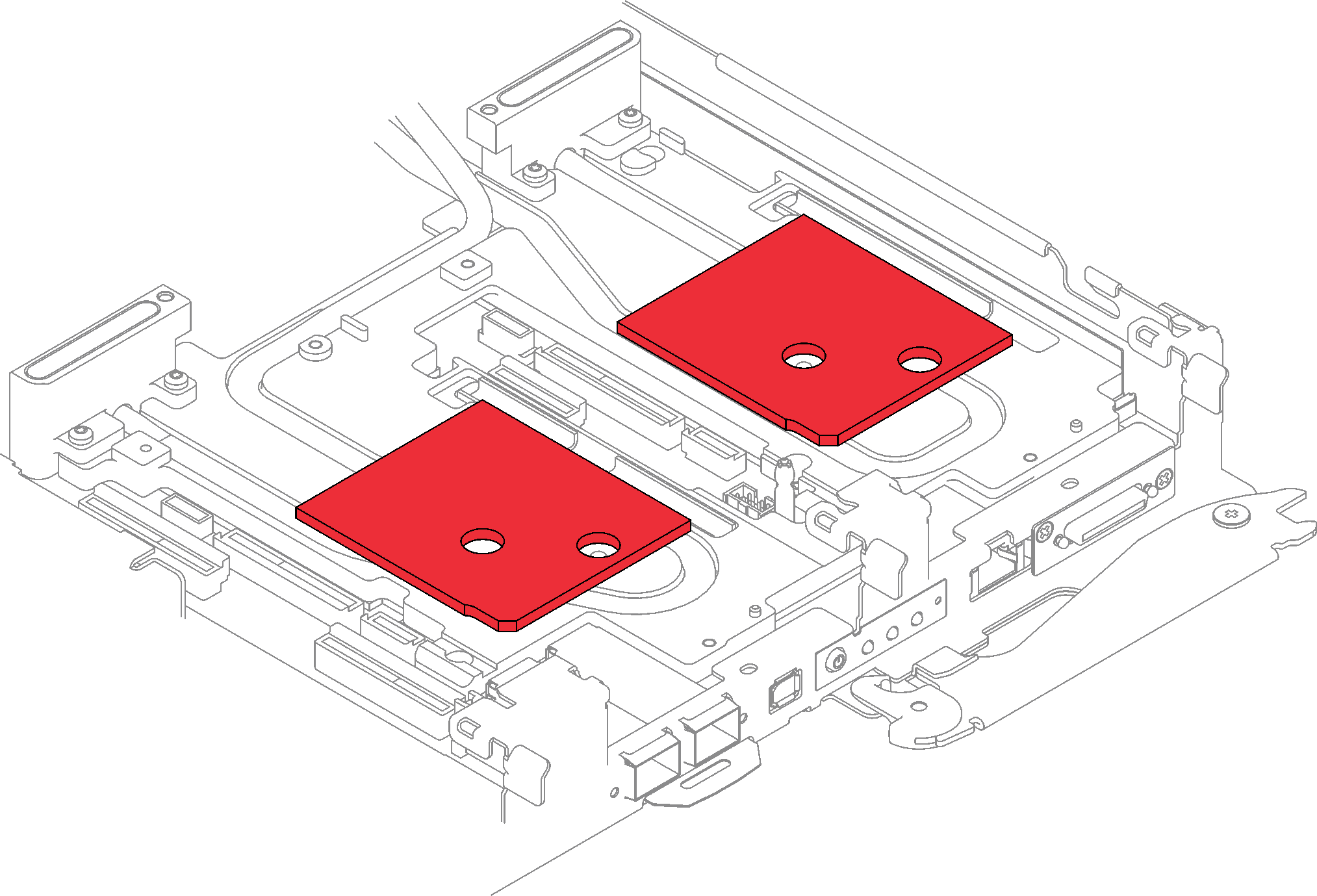
- Install the drive cage assembly.
 Install the drive assembly into the node.
 Secure the 3 screws.
Figure 6. One 15 mm drive cage assembly installation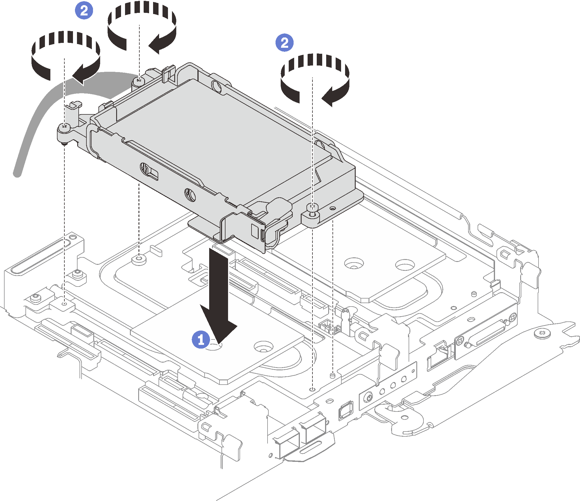 Figure 7. One 7 mm drive cage assembly installation
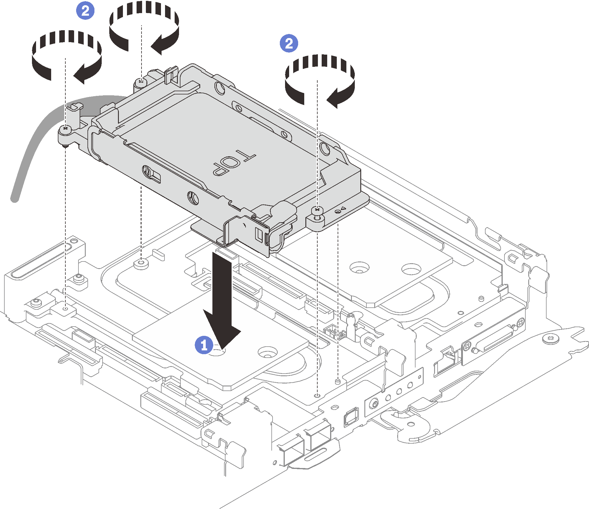 Figure 8. Two 7 mm drive cage assembly installation
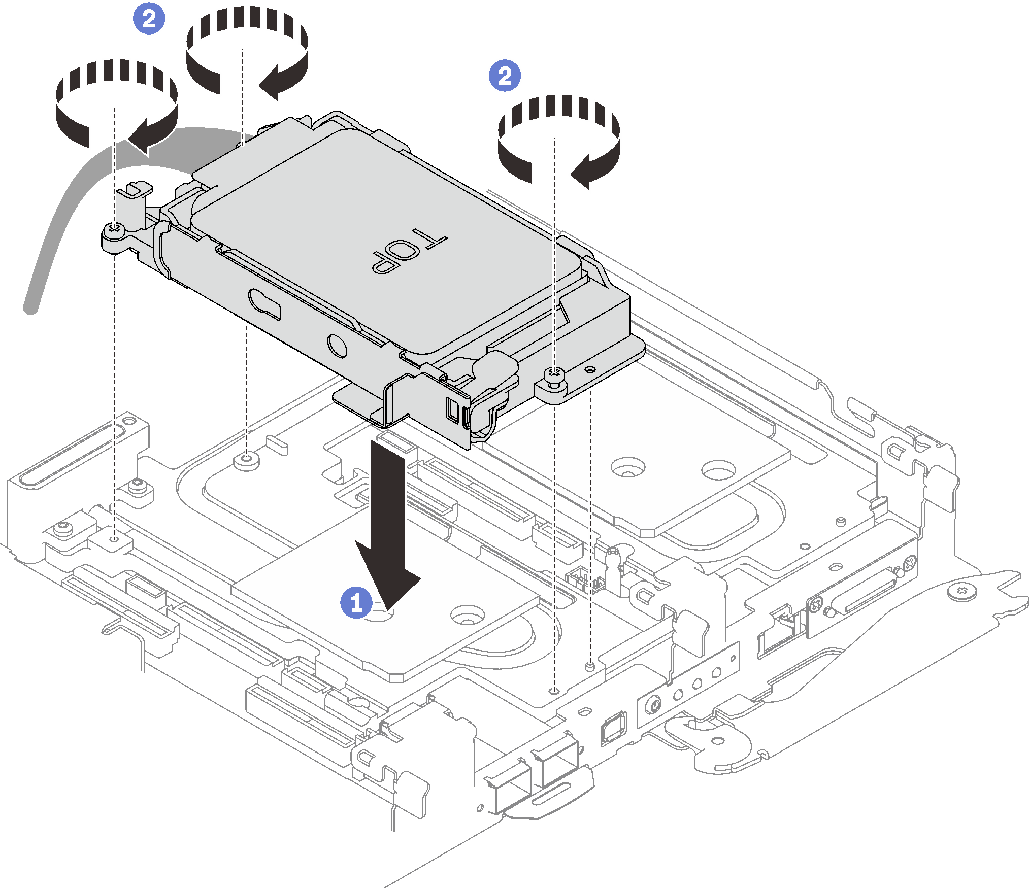
- Connect the drive assembly cable to the system board and route the cable as the following illustration.Figure 9. Drive assembly cable routing
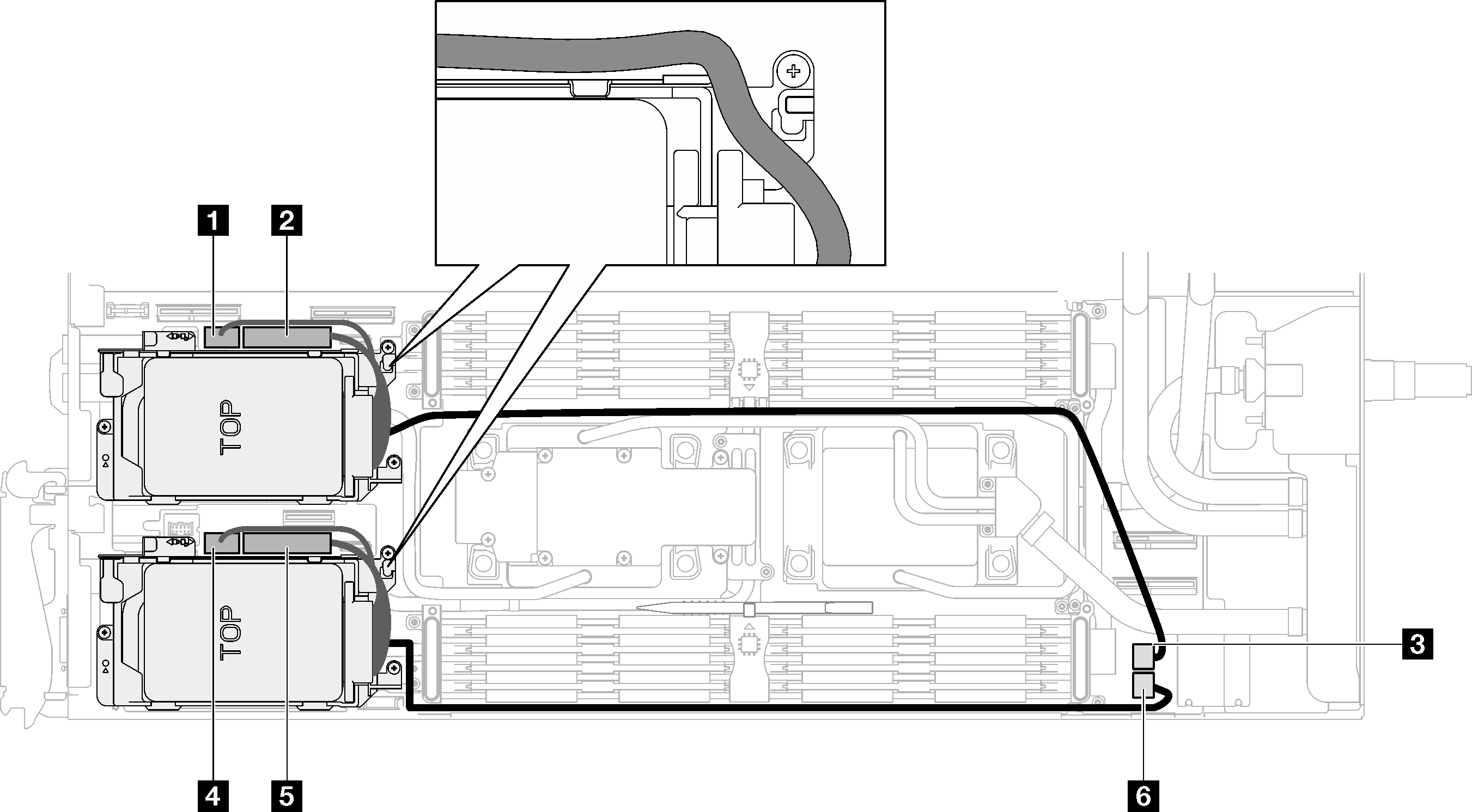
1 SATA 0-1 connector 2 NVMe 0-1 connector 3 Drive power 2 connector 4 SATA 2-3 connector 5 NVMe 2-3 connector 6 Drive power 1 connector
After you finish
Install the cross braces. See Install the cross braces (SD650-I V3).
Install the tray cover. See Install the tray cover.
Install the tray into the enclosure. See Install a DWC tray in the enclosure.
- Connect all required external cables to the solution.NoteUse extra force to connect QSFP cables to the solution.
Check the power LED on each node to make sure it changes from fast blink to slow blink to indicate all nodes are ready to be powered on.
Give documentation feedback