Install a PCIe riser assembly (ConnectX-6)
Use this information to install a PCIe riser assembly with ConnectX-6 adapter.
About this task
Read Installation Guidelines and Safety inspection checklist to ensure that you work safely.
Turn off the corresponding DWC tray that you are going to perform the task on.
Disconnect all external cables from the enclosure.
Use extra force to disconnect QSFP cables if they are connected to the solution.
Ensure you have SD650-I V3 Neptune DWC Waterloop Service Kit
in hand to install components.
- A video of this procedure is available at YouTube.
Procedure
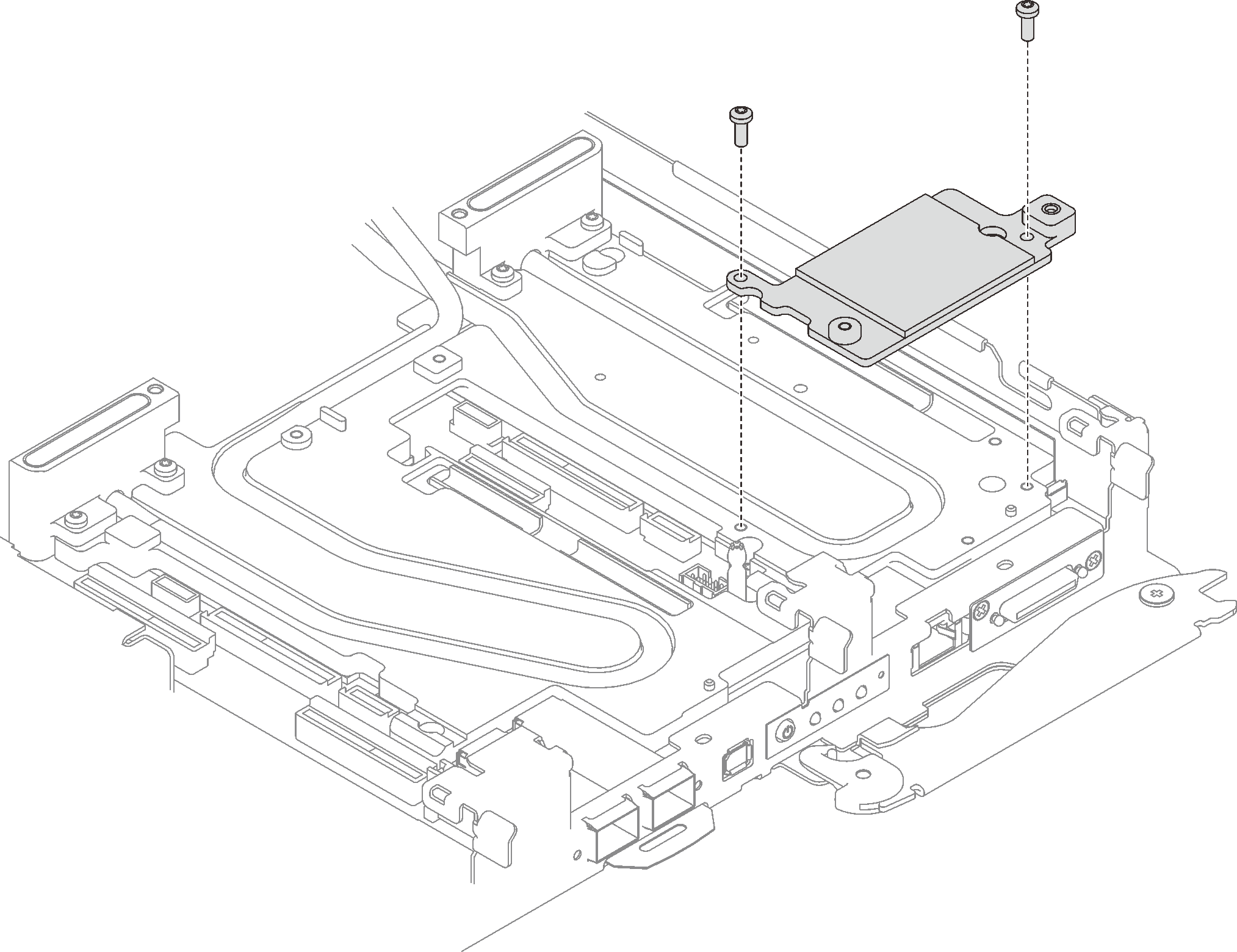
- If the interface plate was removed, place the interface plate onto the node; then, secure the interface plate with two Torx T10 screws.Figure 1. Interface plate installation
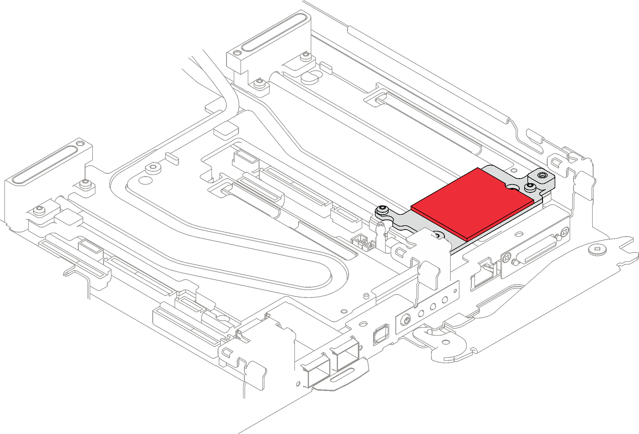
- Replace the interface plate putty pad with a new one. Make sure to follow Gap pad/putty pad replacement guidelines.Figure 2. Interface plate putty pad for CX-6 riser
- Install the PCIe riser assembly.
 Install one hex standoff screw to the cold plate.
 Align the tab on the PCIe riser assembly with the slot on the front of the node; then, insert the PCIe riser assembly onto the system board.
 Secure the riser assembly with one screw.
Figure 3. PCIe riser assembly installation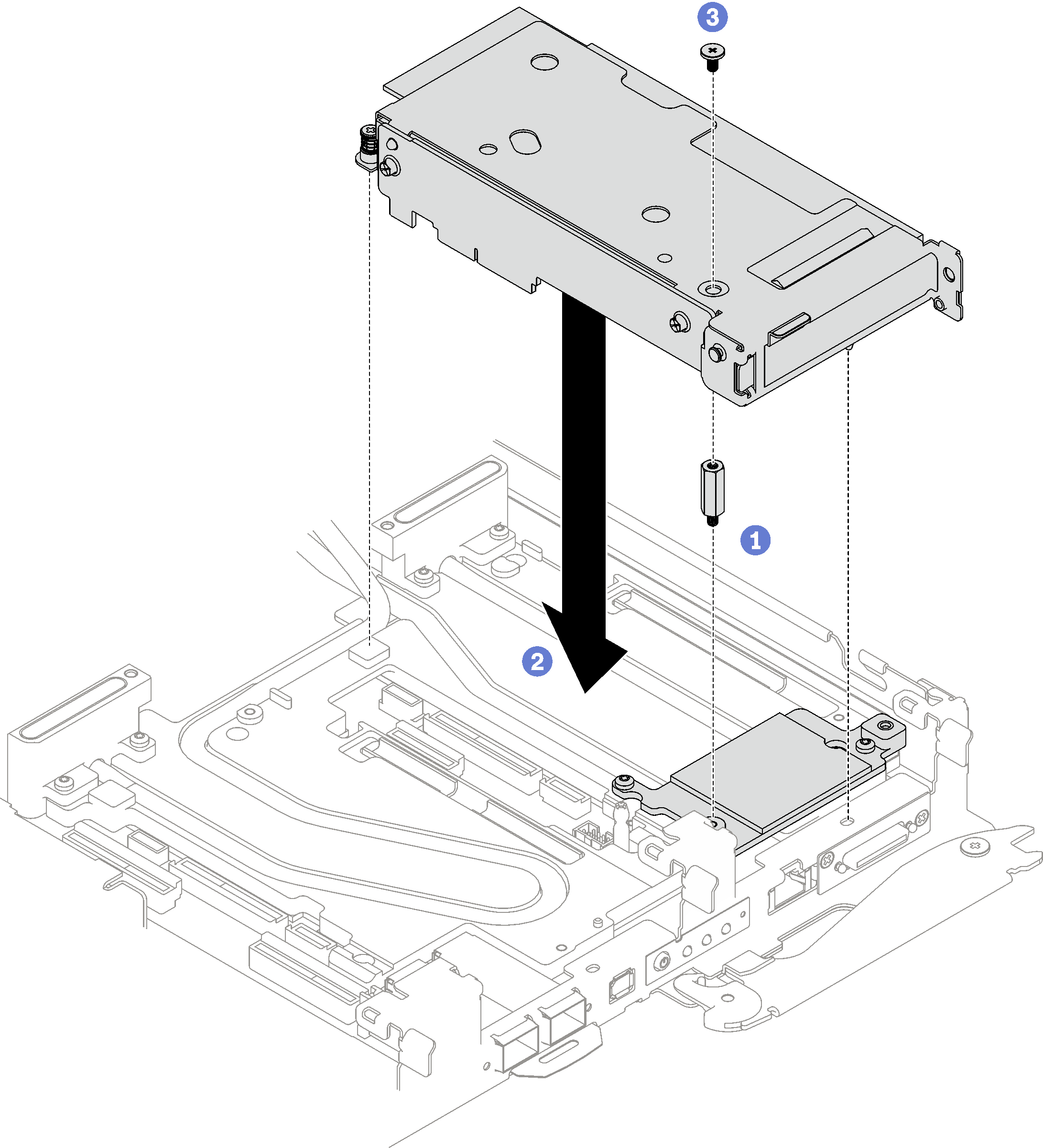
- Secure the PCIe riser assembly.
- Install the clamp bracket and fasten the captive screw.
- Fasten the captive screw on the PCIe riser assembly.
Figure 4. Clamp bracket captive screw installation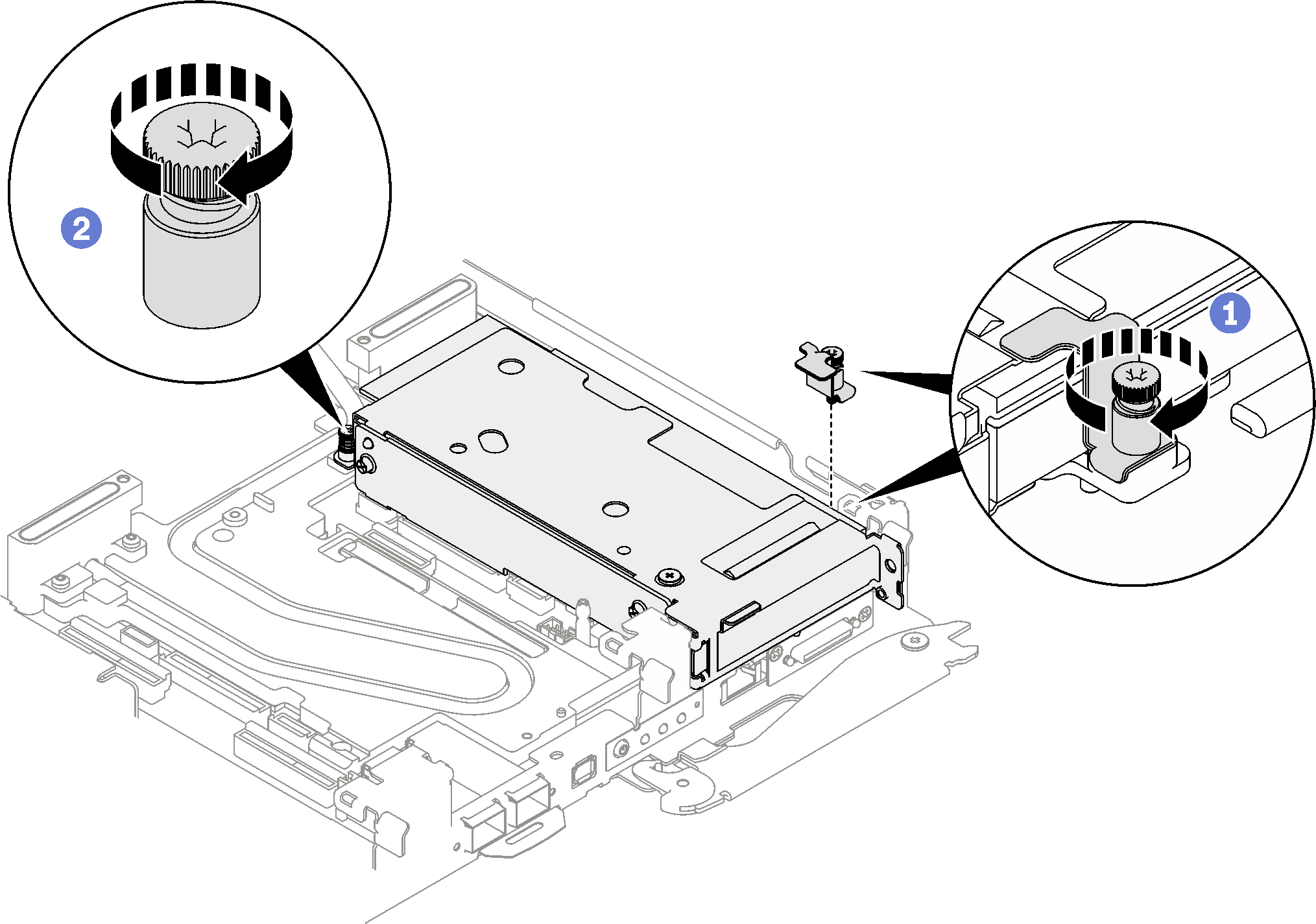
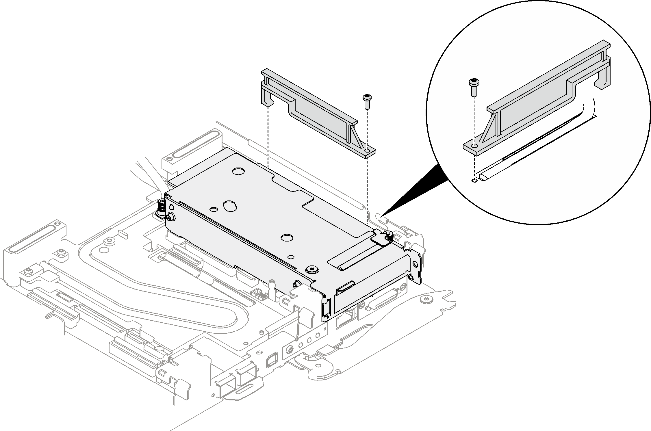
- If necessary, install the heatpipe beam and secure it with one screw.Figure 5. Heatpipe beam installation
Install the tray cover. See Install the tray cover.
Install the tray into the enclosure. See Install a DWC tray in the enclosure.
- Connect all required external cables to the solution.NoteUse extra force to connect QSFP cables to the solution.
Check the power LED on each node to make sure it changes from fast blink to slow blink to indicate all nodes are ready to be powered on.