Install the M.2 backplane assembly
Use this information to install the M.2 backplane assembly.
About this task

To avoid a shock hazard:
- Connect all power cords to a properly wired and grounded electrical outlet/source.
- Connect any equipment that will be attached to this product to properly wired outlets/sources.
- When possible, use one hand only to connect or disconnect signal cables.
- Never turn on any equipment when there is evidence of fire, water, or structural damage.
- The device might have more than one power cord, to remove all electrical current from the device, ensure that all power cords are disconnected from the power source.
Read Installation Guidelines and Safety inspection checklist to ensure that you work safely.
Turn off the corresponding DWC tray that you are going to perform the task on.
Ensure you have SD650-I V3 Neptune DWC Waterloop Service Kit
in hand to install components.
Go to Drivers and Software download website for ThinkSystem SD650 V3 to see the latest firmware and driver updates for your server.
Go to Update the firmware for more information on firmware updating tools.
- A video of this procedure is available at YouTube.
Procedure
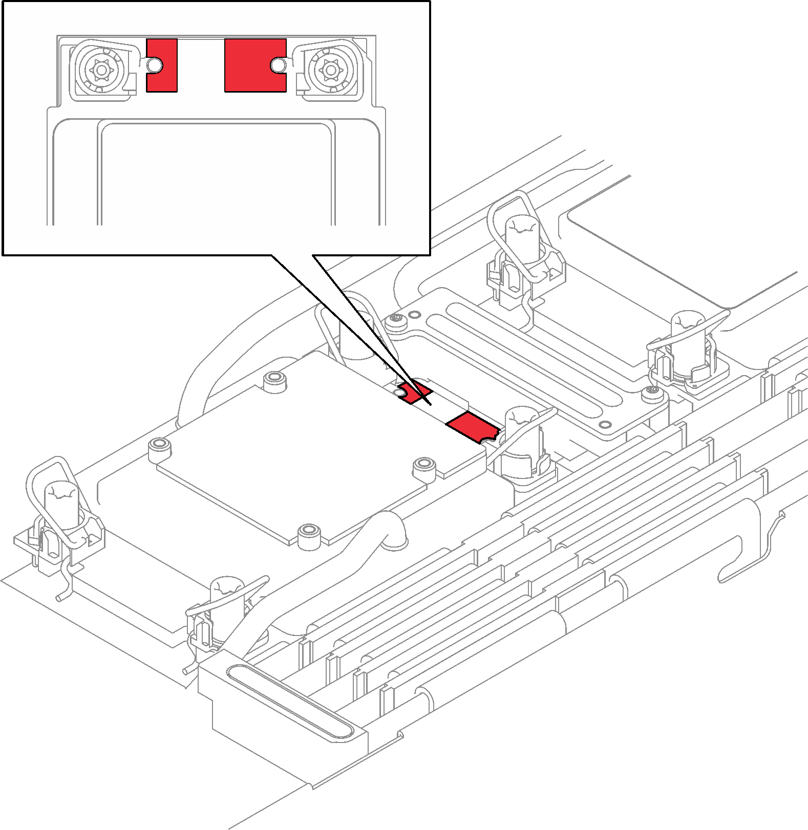
- Replace the putty pad on the processor (Processor 1) cold plate with a new one. Make sure to follow Gap pad/putty pad replacement guidelines.Figure 1. Gap pad on processor cold plate
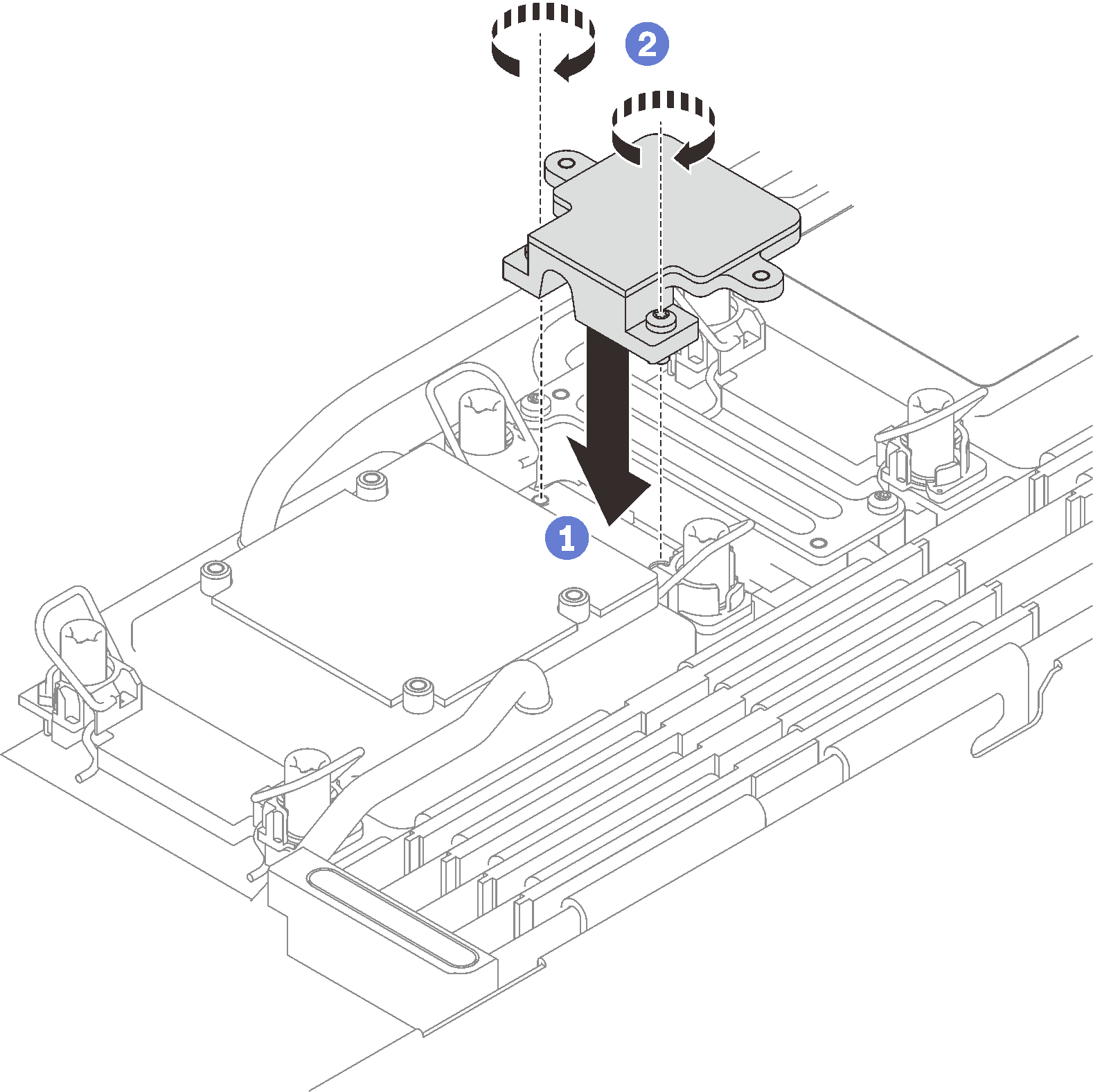
- Install the M.2 backplane cold plate.
 Place the M.2 cold plate onto the front processor (Processor 1) cold plate.
 Fasten the two screws to secure the M.2 backplane cold plate to the processor cold plate.
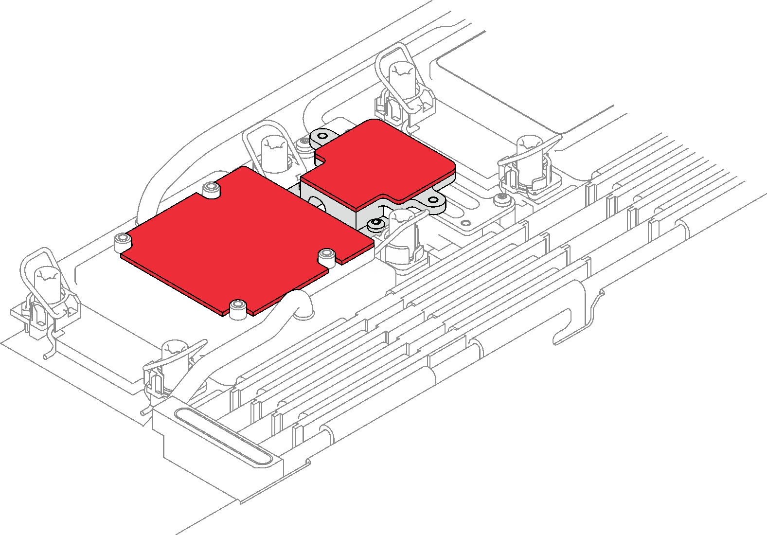
- Replace the putty pad on the processor (Processor 1) cold plate and the M.2 backplane cold plate with a new ones. Make sure to follow Gap pad/putty pad replacement guidelines.Figure 2. Gap pad on processor cold plate and M.2 backplane cold plate
- Install the M.2 backplane assembly.
- Connect the cable to the M.2 backplane assembly.
- Install the M.2 backplane assembly into the node.
 Secure the six screws.
Figure 3. M.2 backplane assembly installation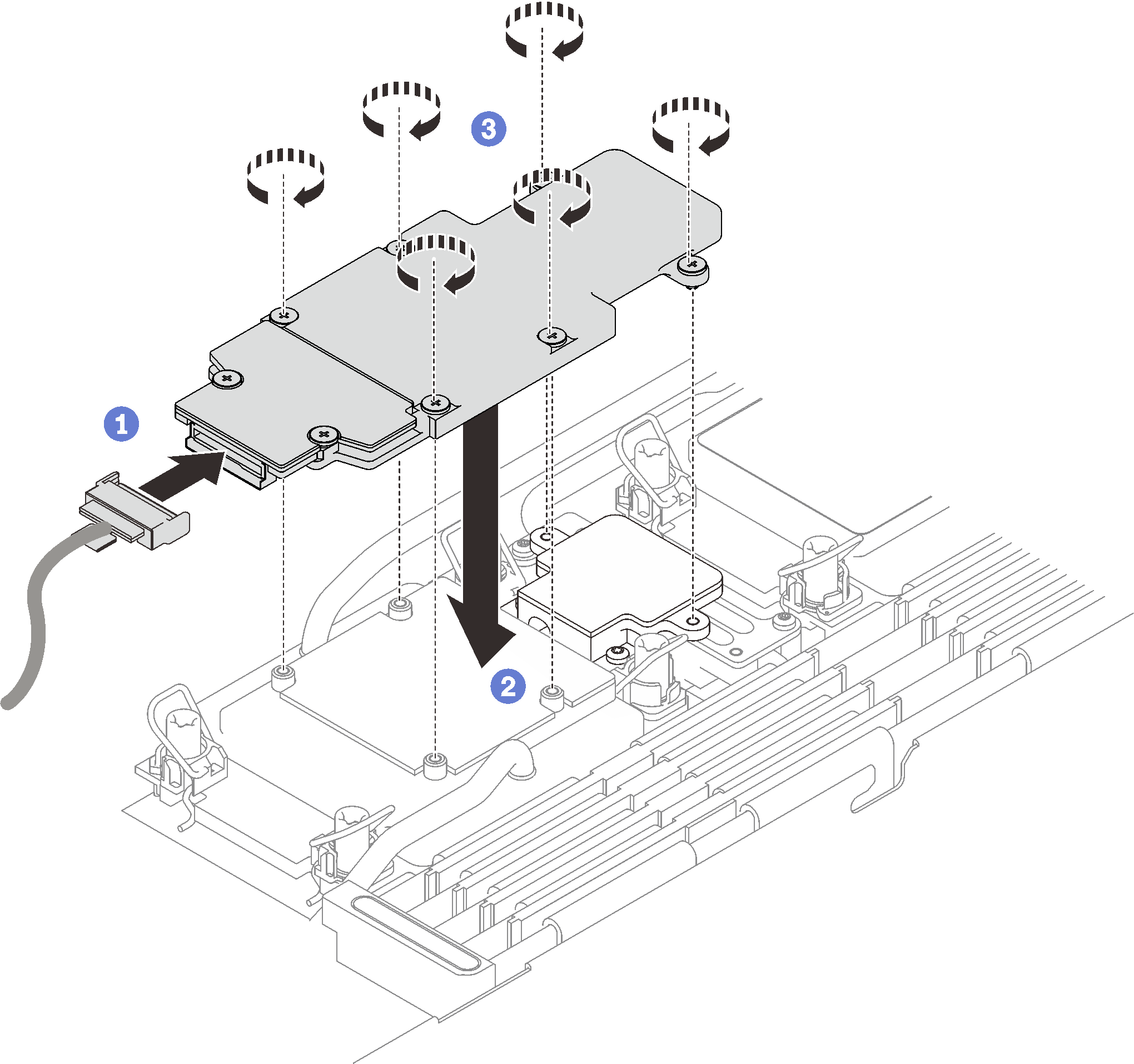
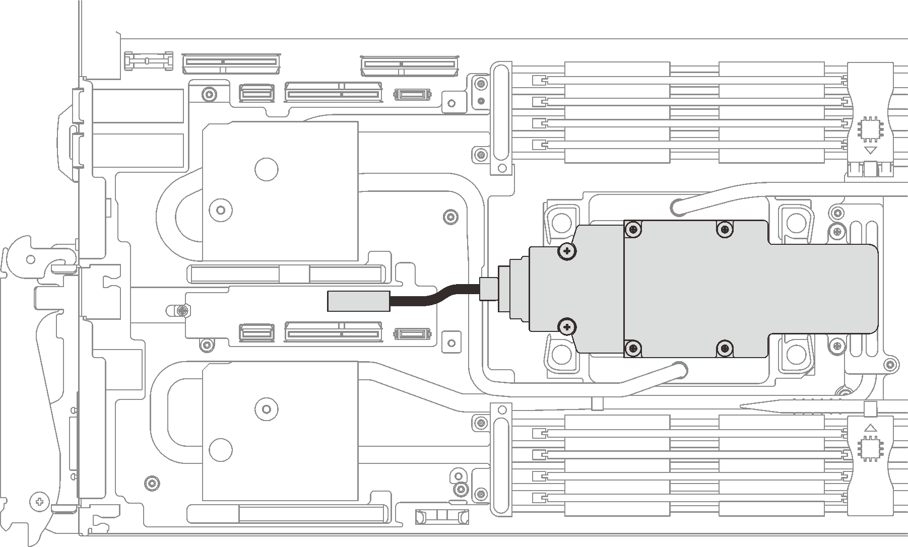
- Connect the cable to the system board.Figure 4. M.2 backplane assembly cable installation
Install the cross braces. See Install the cross braces (SD650-I V3).
Install the tray cover. See Install the tray cover.
Install the tray into the enclosure. See Install a DWC tray in the enclosure.
- Connect all required external cables to the solution.NoteUse extra force to connect QSFP cables to the solution.
Check the power LED on each node to make sure it changes from fast blink to slow blink to indicate all nodes are ready to be powered on.