Install the power distribution board
Use this information to install the power distribution board.
About this task

To avoid a shock hazard:
- Connect all power cords to a properly wired and grounded electrical outlet/source.
- Connect any equipment that will be attached to this product to properly wired outlets/sources.
- When possible, use one hand only to connect or disconnect signal cables.
- Never turn on any equipment when there is evidence of fire, water, or structural damage.
- The device might have more than one power cord, to remove all electrical current from the device, ensure that all power cords are disconnected from the power source.
Read Installation Guidelines and Safety inspection checklist to ensure that you work safely.
Ensure you have SD650-I V3 Neptune DWC Waterloop Service Kit
in hand to install components.
| Screwdriver Type | Screw Type |
|---|---|
| Torx T10 head screwdriver | Torx T10 screw |
| Torx T30 head screwdriver | Torx T30 screw |
| Phillips #1 head screwdriver | Phillips #1 screw |
| Phillips #2 head screwdriver | Phillips #2 screw |
Go to Drivers and Software download website for ThinkSystem SD650 V3 to see the latest firmware and driver updates for your server.
Go to Update the firmware for more information on firmware updating tools.
- A video of this procedure is available at YouTube.
Procedure
- Install the power distribution board.
 Tilt the power distribution board and align it with the hole; then, slide it into place.
 Gently push the power distribution board connector to ensure it is connected to the system board.
 Fasten the five Phillips #1 screws.
NoteUse a 3/16" hex head screwdriver to ensure the proper removal and installation.
Figure 1. Power distribution board installation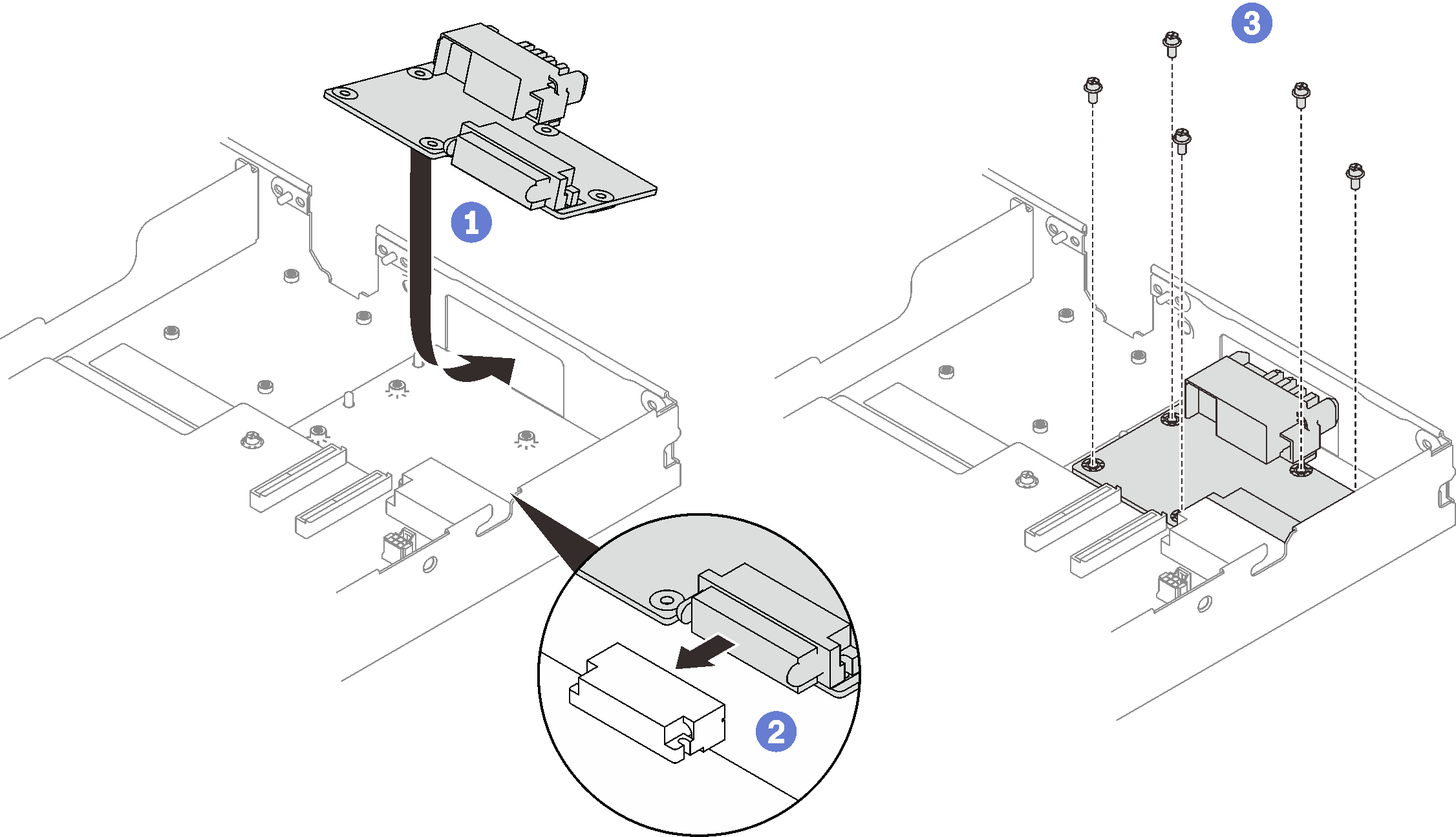
- Check the gap pads on the water loop, if any of them are damaged or detached, replace them with the new ones.Figure 2. Water loop gap pads
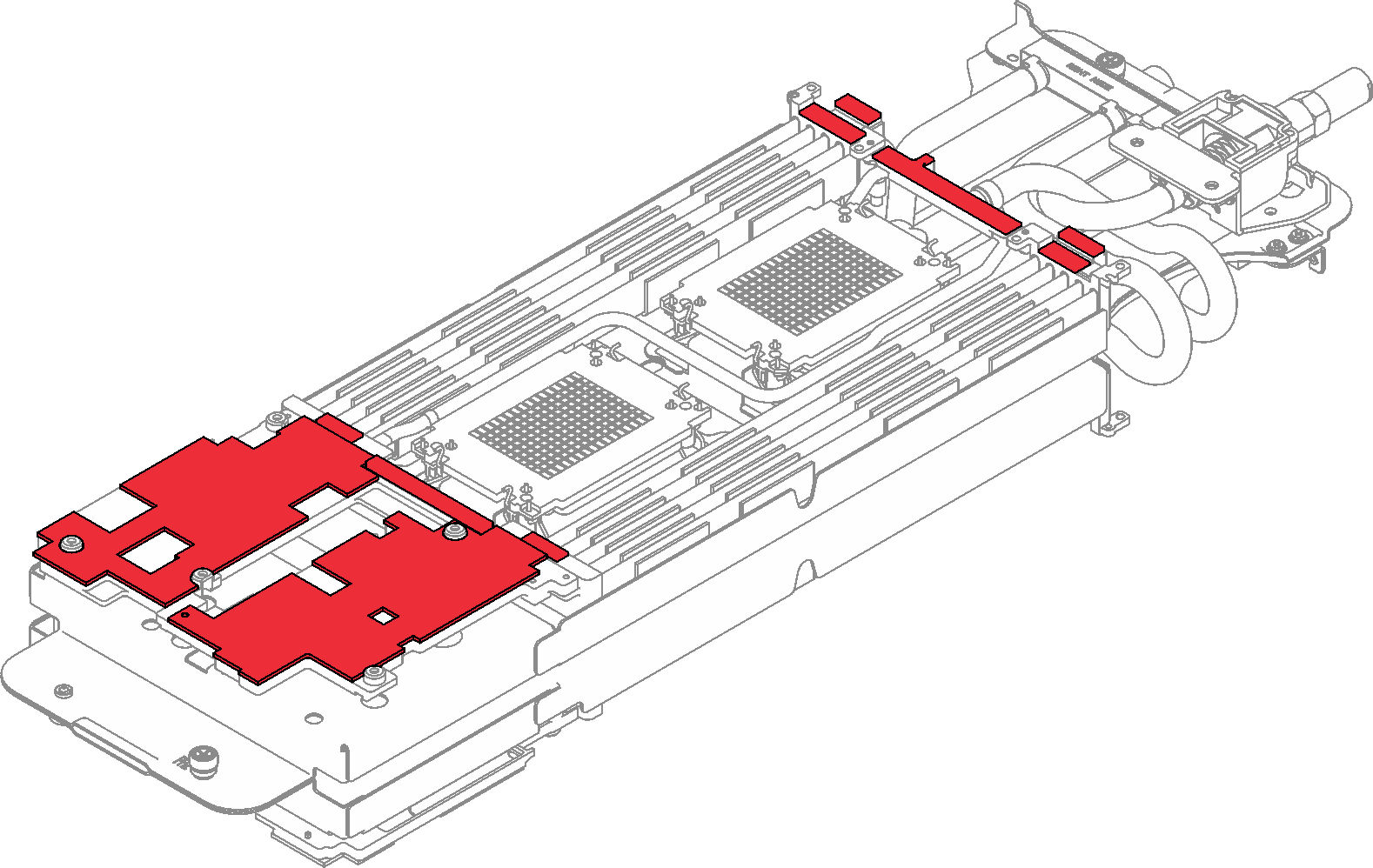
Make sure to follow Gap pad/putty pad replacement guidelines.
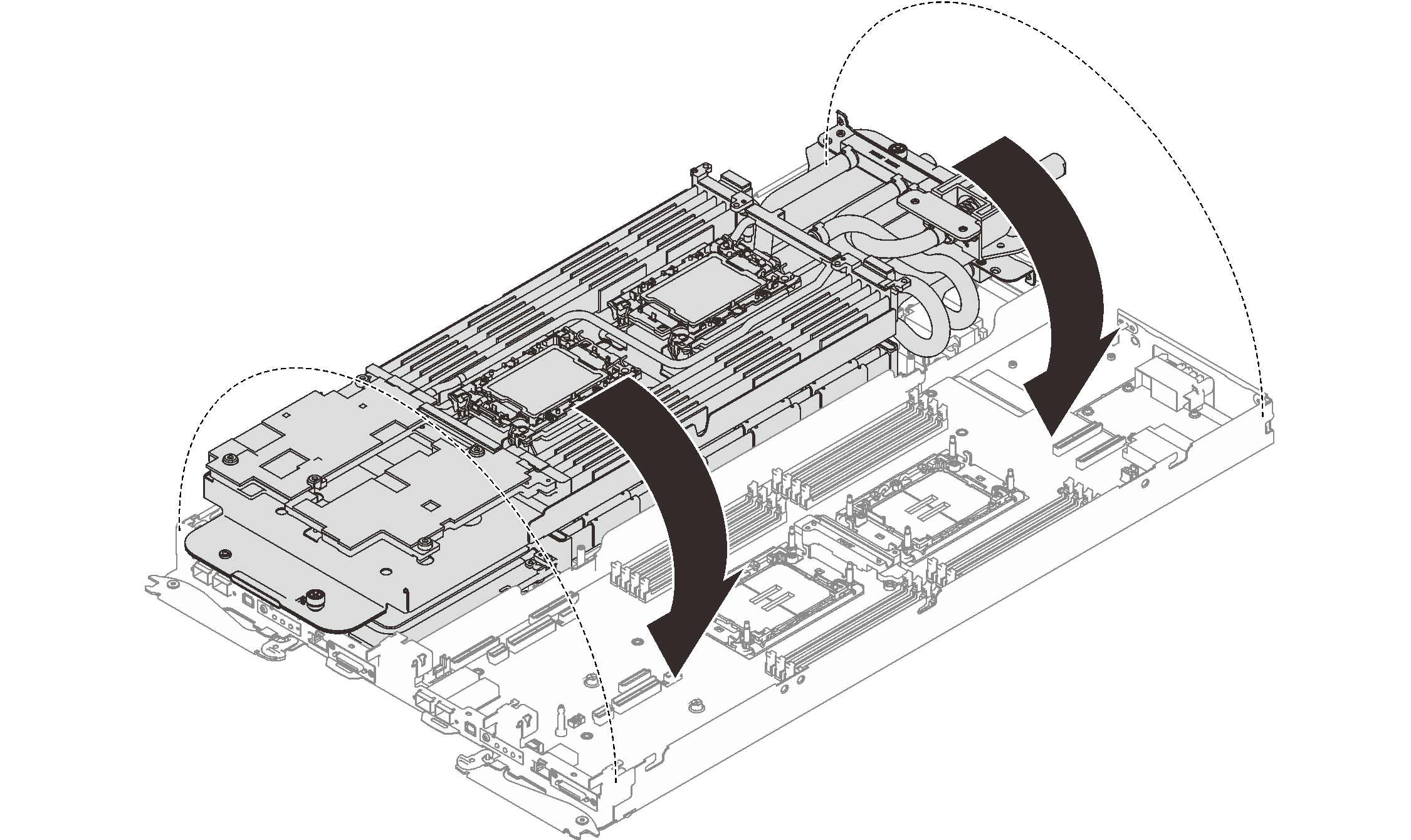
- Carefully rotate the top side of the water loop, position the water loop on the two guide pins near the rear of the node; then, gently put the water loop down and ensure it is firmly seated on the system board.Figure 3. Water loop installation
- Ensure the processors are secured properly.
- Rotate the anti-tilt wire bails (8x anti-tilt wire bails per node) outwards to the locked position.
- Fully tighten all Torx T30 captive screws (8x Torx T30 captive screws per node) on cold plates with a general screwdriver until they stop, following the installation sequence shown on the cold plate label.
NoteFor reference, the torque required for the screws to be fully tightened/removed is 10+/- 2.0 lbf-in, 1.1+/- 0.2 N-m.AttentionTo prevent damage to components, make sure that you follow the indicated tightening sequence.Figure 4. Processors installation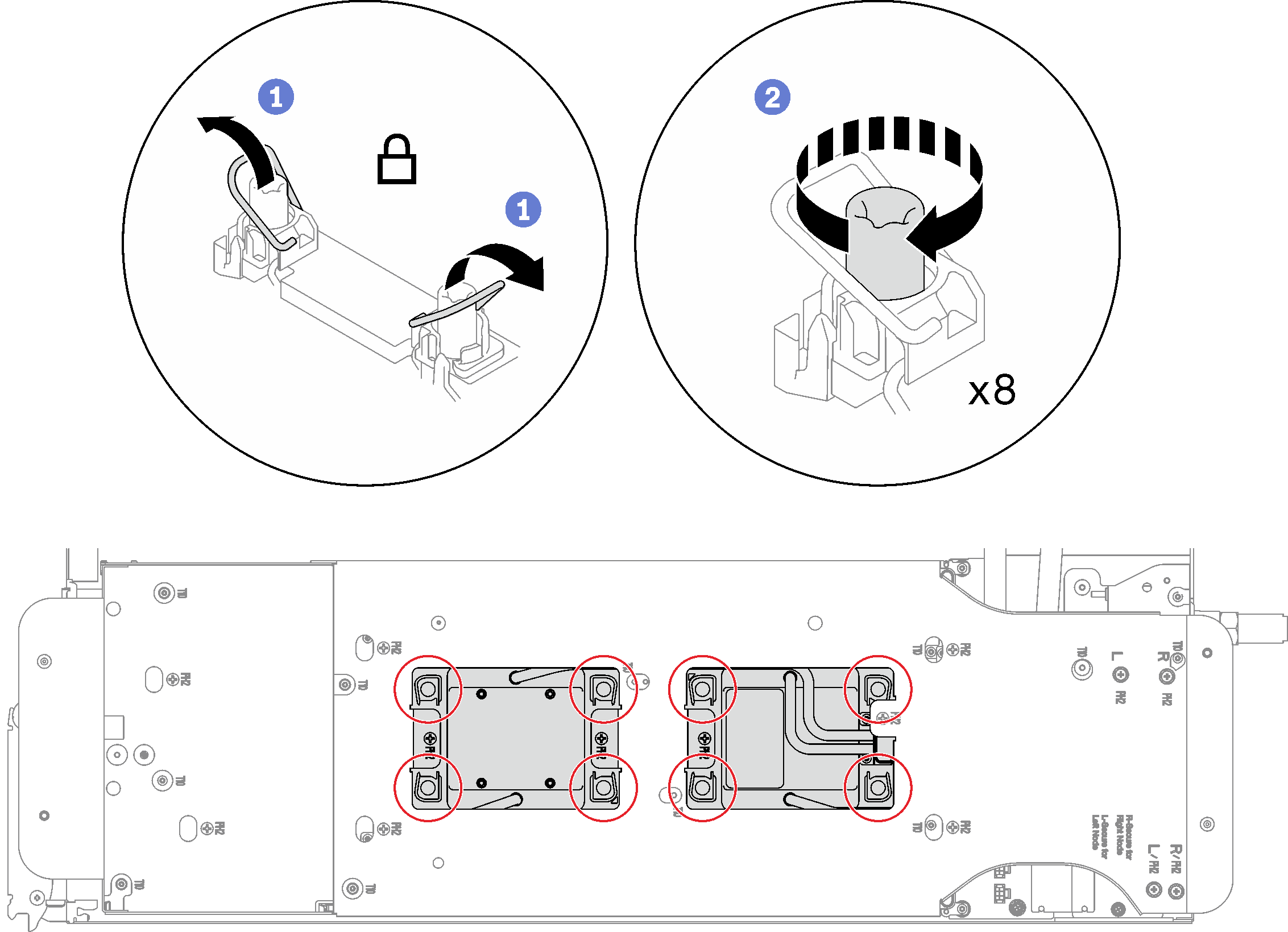
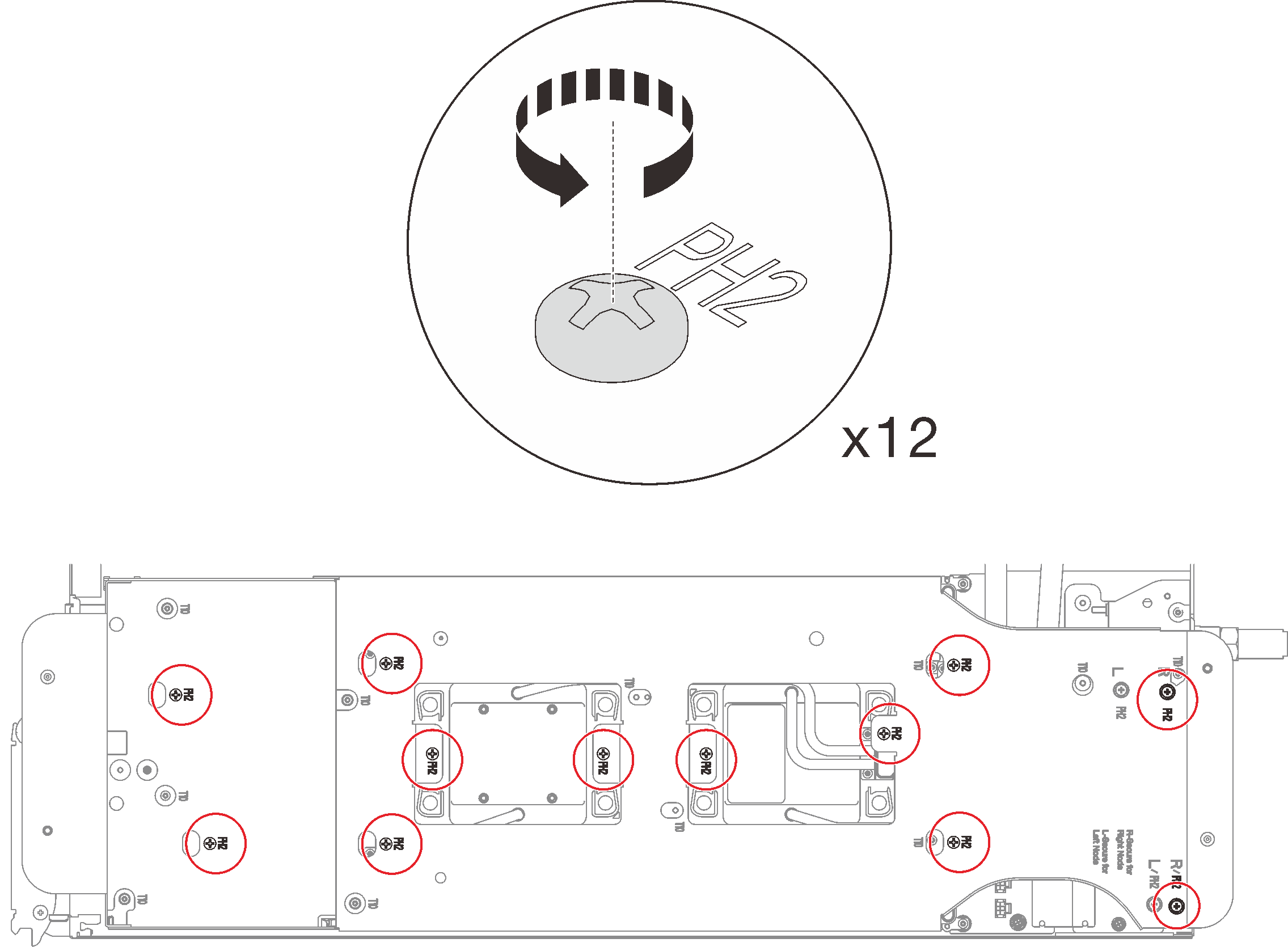
- Loosen water loop carrier screws (12x Phillips #2 screws per node).Figure 5. Loosening water loop carrier screws
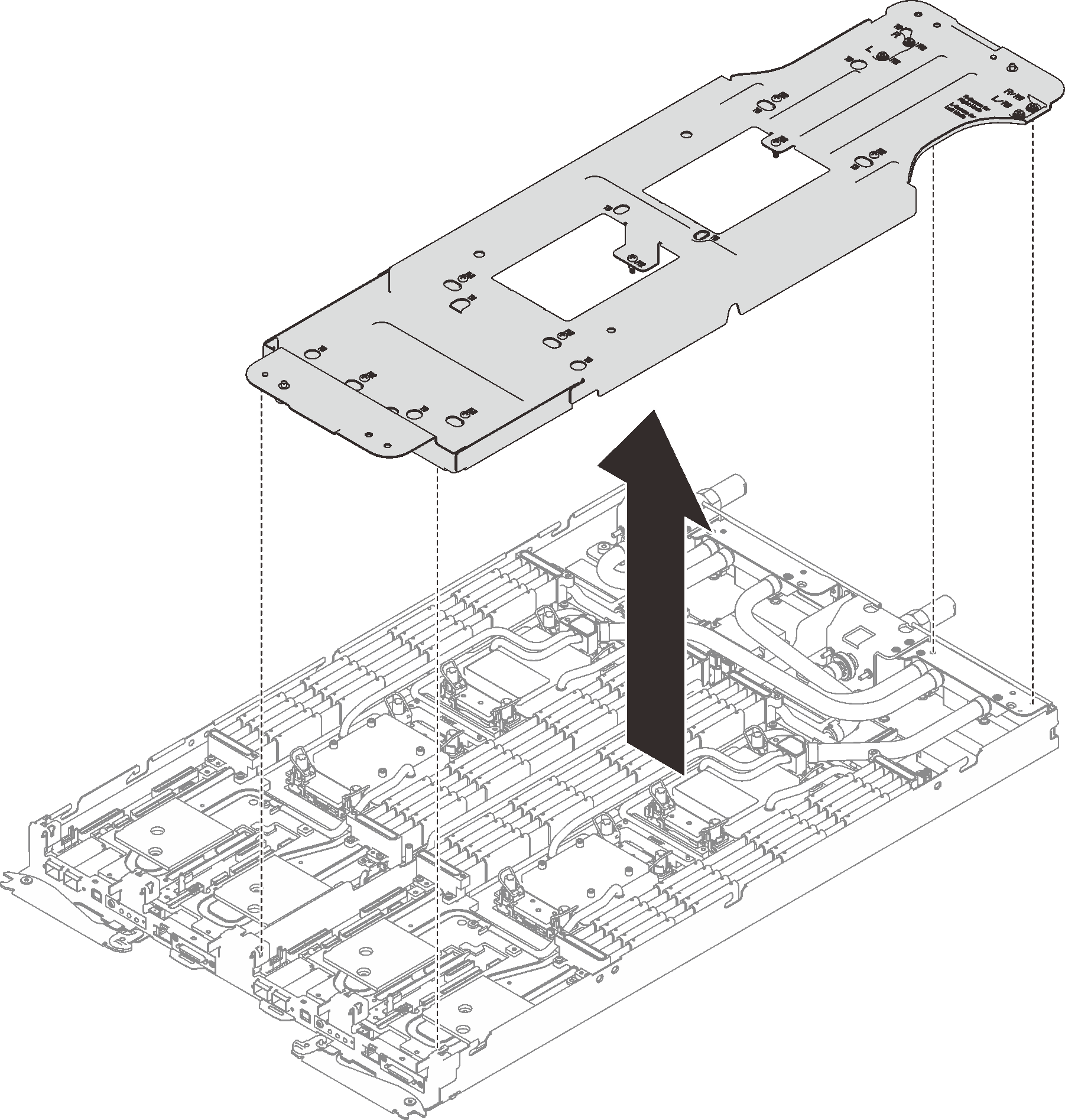
- Carefully lift the water loop carrier up and away from the water loop.Figure 6. Water loop carrier removal
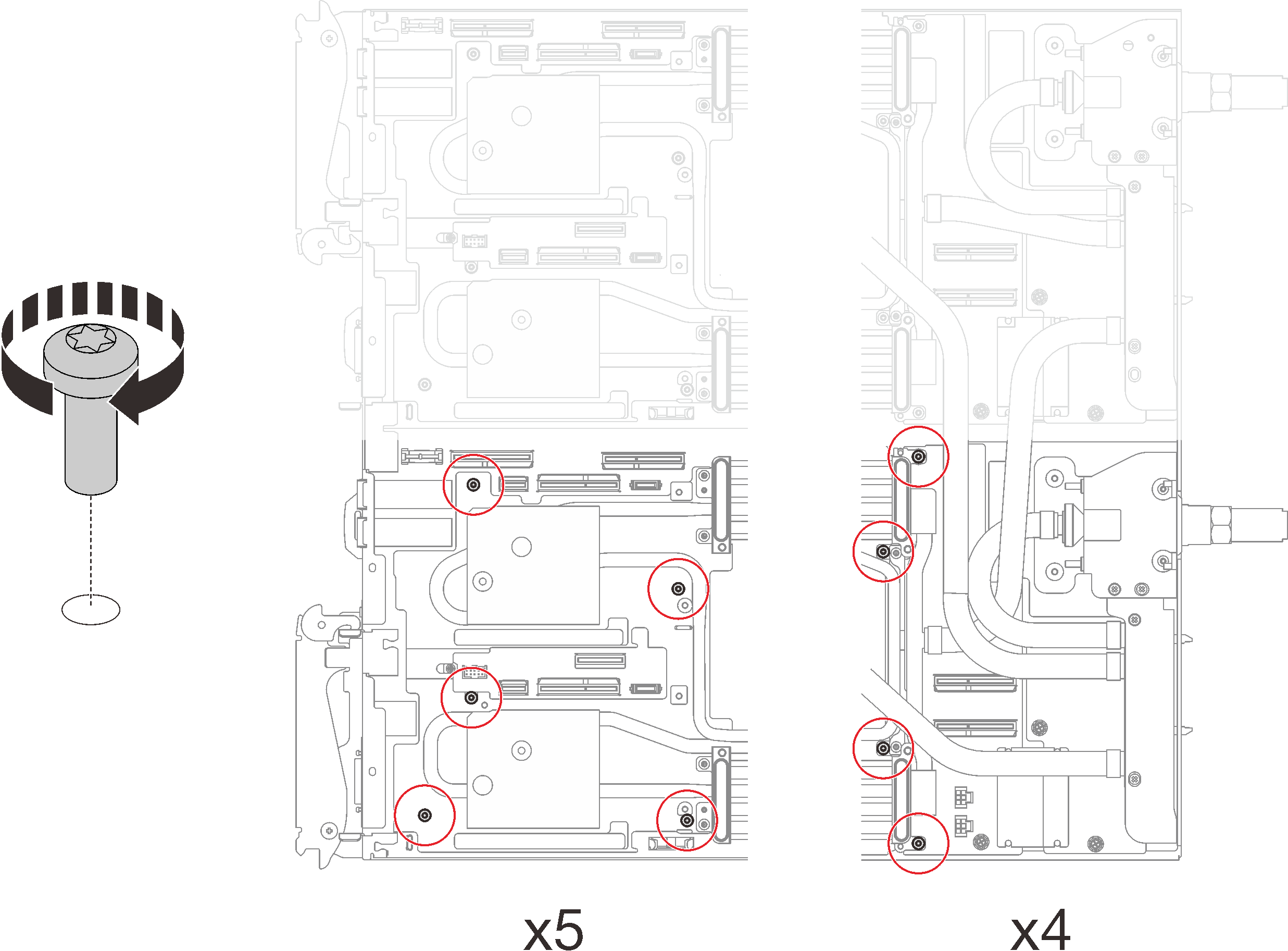
- Install water loop screws (9x Torx T10 screws per node) with a torque screwdriver set to the proper torque.NoteFor reference, the torque required for the screws to be fully tightened/removed is 5.0+/- 0.5 lbf-in, 0.55+/- 0.05 N-M.Figure 7. Water loop screws installation
- Install the following screws to secure the quick connect.
Two Torx T10 screws (per node) on the quick connect.
Five Torx T10 screws (per node) on the rear of the node.
Figure 8. Quick connect screw installation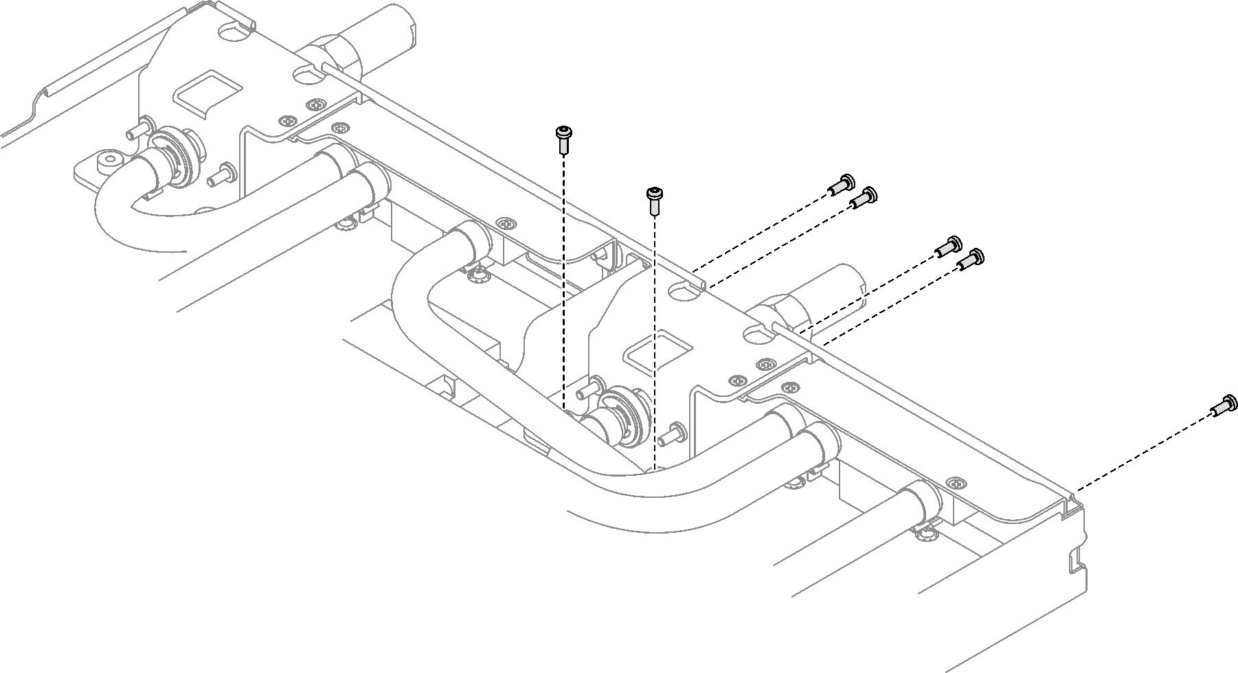
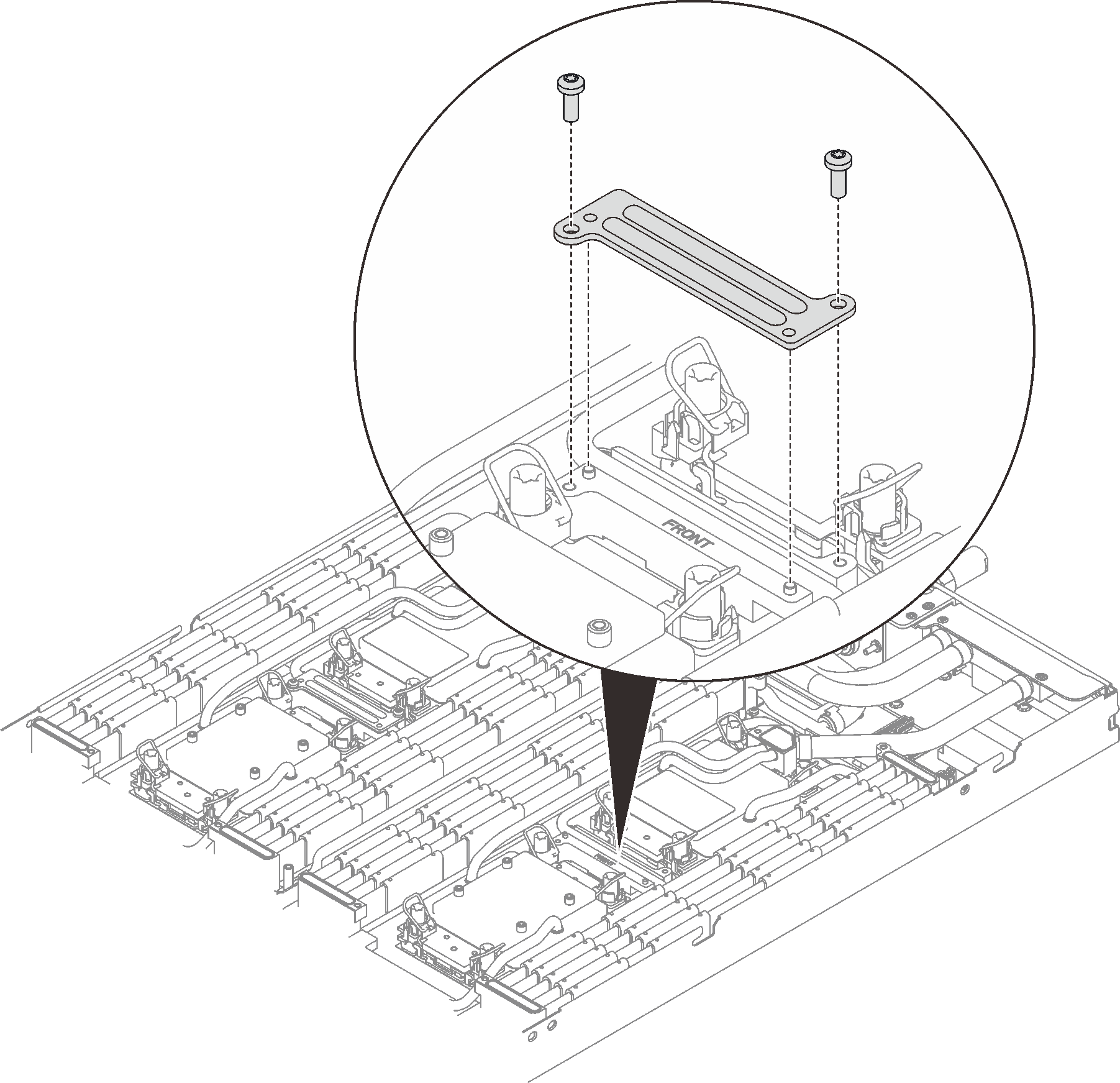
- Install the VR clamp plate into the node and install Torx T10 screws (2x Torx T10 screw per nods).Figure 9. VR clamp plate installation
Install the cross braces. See Install the cross braces (SD650-I V3).
Install the tray cover. See Install the tray cover.
Install the tray into the enclosure. See Install a DWC tray in the enclosure.
- Connect all required external cables to the solution.NoteUse extra force to connect QSFP cables to the solution.
Check the power LED on each node to make sure it changes from fast blink to slow blink to indicate all nodes are ready to be powered on.