System-board switches
The following illustration shows the location and description of the switches.
Note
If there is a clear protective sticker on the top of the switch blocks, you must remove and discard it to access the switches.
Important
Before you change any switch settings or move any jumpers, turn off the solution; then, disconnect all power cords and external cables. Review the following information:
- Any system-board switch or jumper block that is not shown in the illustrations in this document are reserved.
Figure 1. Switches on compute node system board
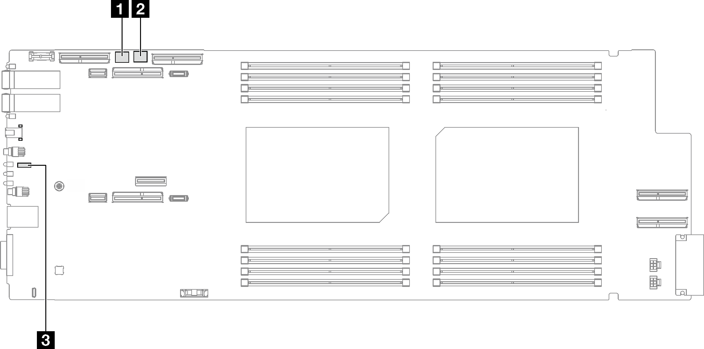
| 1 SW5 switch block | 2 SW13 switch block |
| 3 Jumper 44 |
| Switch number | Switch name | Usage description | |
|---|---|---|---|
| On | Off | ||
1 | BMC reset | Force hot reset BMC chip | (Default) Normal. |
3 | Machine Engine (ME) firmware security override | ME update by jumper | (Default) Normal. |
4 | Password override | Overrides the power-on password | (Default) Normal. |
| Switch number | Switch name | Usage description | |
|---|---|---|---|
| On | Off | ||
3 | Clear CMOS | Clear CMOS data | (Default) Normal. |
5 | Serial select | Sends the XCC to the serial port | (Default) Send the serial input output (SIO) to the front serial port. |
| Switch number | Switch name | Usage description | |
|---|---|---|---|
| On | Off | ||
44 | BMC Boot from Backup | Request XCC to boot using a backup of the XCC firmware | (Default) XCC will boot by using the primary XCC firmware. |
Give documentation feedback