Front view
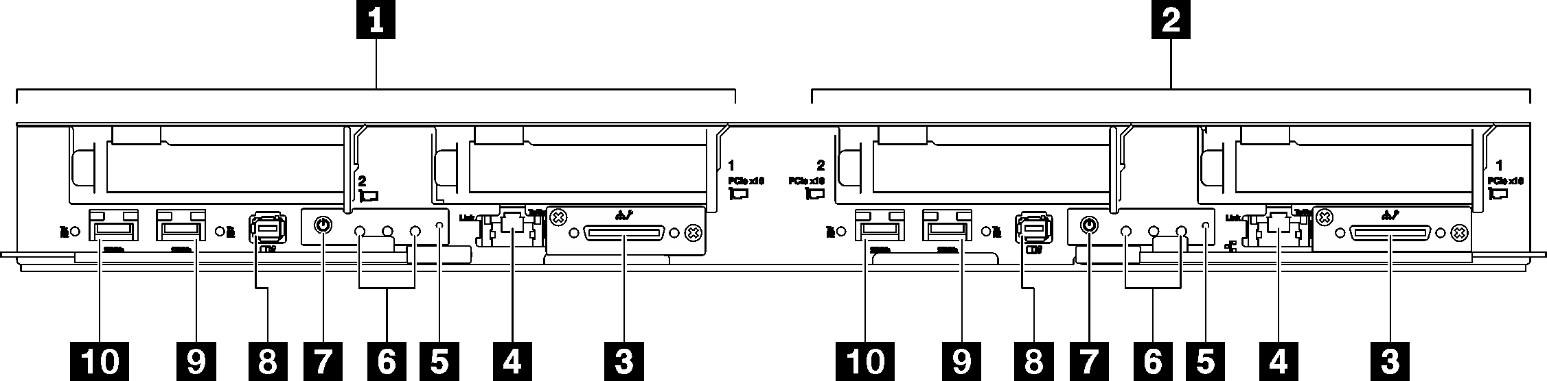
The following illustration shows the controls, LEDs, and connectors on the front of the solution.
The 6U enclosure supports up to six trays.
Each tray contains two nodes; one left node and one right node (when viewed from front of enclosure).
SD650 V3 tray contains two compute nodes.
SD650 V3 tray
Shared I/O configuration requires specific power on and power off sequence for the two nodes, see below:
Power on sequence: first, power on the node with main adapter (right node); then, power on the node with auxiliary adapter (left node).
Power off sequence: first, power off the node with auxiliary adapter (left node); then, power off the node with main adapter (right node).
1 Compute node / Left node (odd bay numbers) | 6 Front operator panel LEDs. See Front LEDs for more information. |
2 Compute node / Right node (even bay numbers) | 7 Node power button with LED. See Front LEDs for more information. |
| 3 KVM breakout cable connector The KVM breakout cable includes VGA connector, serial port connector, and USB 3.0 (5 Gbps) / 2.0 connector. XCC mobile management is supported by USB 2.0 connector on the KVM breakout cable only. For more information, see KVM breakout cable. | 8 External Diagnostics Handset connector. See External Diagnostics Handset for more information. |
| 4 1 Gb RJ45 Ethernet port with share-NIC feature for Lenovo XClarity Controller. See Front LEDs for more information. Lenovo XClarity Controller connection is mutually exclusive between RJ45 Ethernet connector and 25Gb SFP28 Port 1. | 9 25 Gb SFP28 Ethernet port (Port 2). See Front LEDs for more information. |
| 5 NMI button. Press this button to force a nonmaskable interrupt to the processor. You might have to use a pen or the end of a straightened paper clip to press the button. You can also use it to force a blue-screen memory dump. Use this button only when you are directed to do so by Lenovo Support. | 10 25 Gb SFP28 Ethernet port (Port 1) with share-NIC feature for Lenovo XClarity Controller. See Front LEDs for more information. Lenovo XClarity Controller connection is mutually exclusive between RJ45 Ethernet connector and 25Gb SFP28 Port 1. |