Remove the manifold
Use this information to remove the manifold.
CAUTION
The water might cause irritation to the skin and eyes. Avoid direct contact with the lubricant.
S002
CAUTION
The power-control button on the device and the power switch on the power supply do not turn off the electrical current supplied to the device. The device also might have more than one power cord. To remove all electrical current from the device, ensure that all power cords are disconnected from the power source.
S038

CAUTION
Eye protection should be worn for this procedure.
Attention
Ensure proper handling procedures are followed when working with any chemically treated water used in the compute rack cooling system. Ensure that material safety data sheets (MSDS) and safety information are provided by the water chemical treatment supplier and that proper personal protective equipment (PPE) is available as recommended by the water chemical treatment supplier. Protective gloves and eyewear may be recommended as a precaution.
Before you remove the manifold:
Read the Installation Guidelines to ensure that you work safely.
Complete the following steps to remove the manifold.
- At the front of the rack, close both Eaton ball valves.Figure 1. Eaton ball valves closed
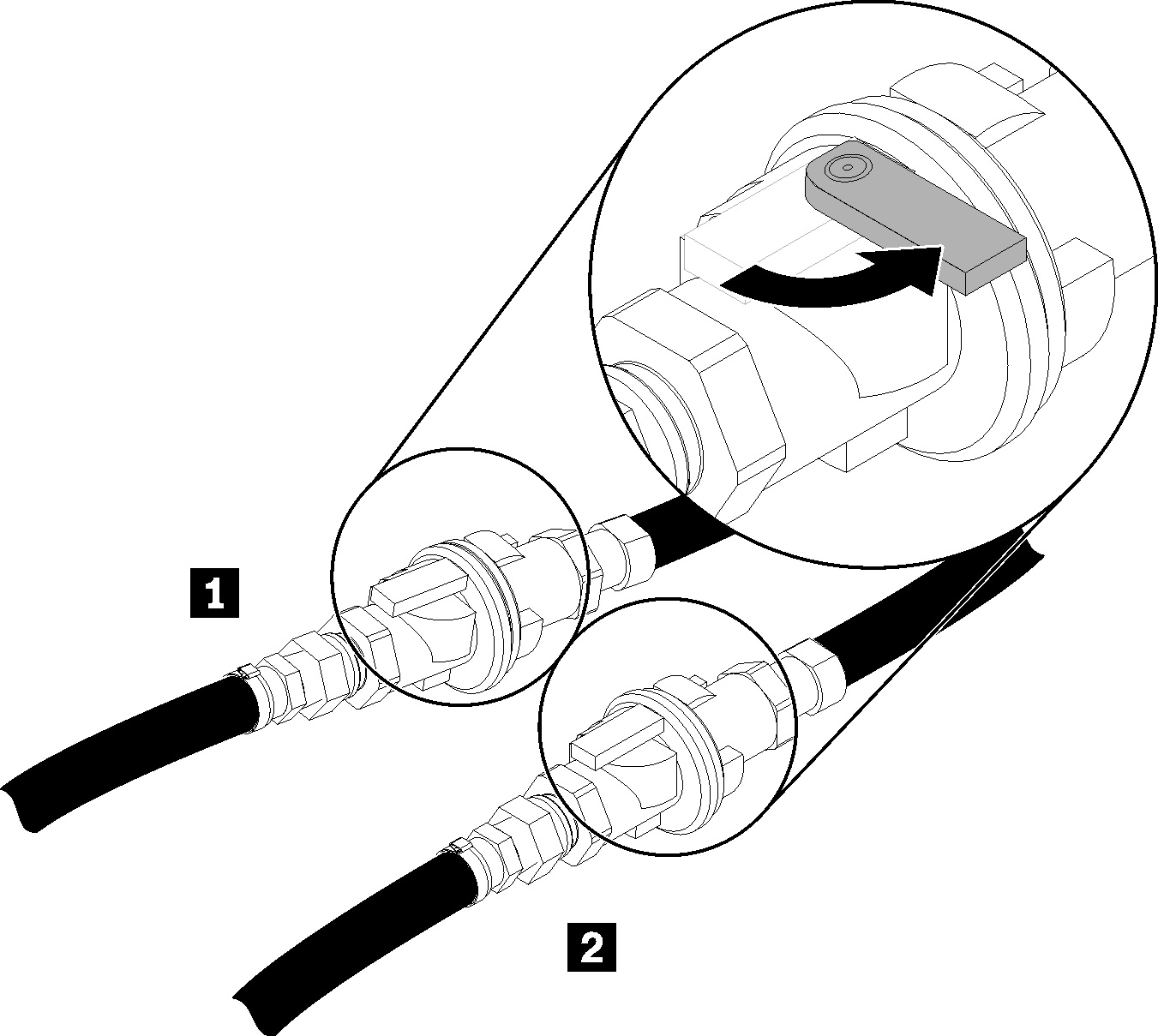
Table 1. Eaton ball valves 1 Rack supply 2 Rack return - Remove EMC shields on both sides of the top enclosure.Figure 2. EMC shields removal
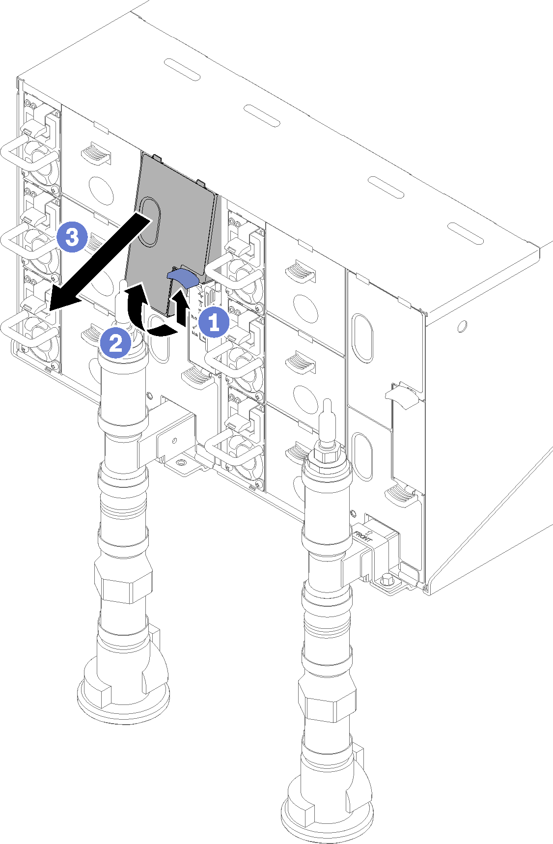 Figure 3. EMC shields removal
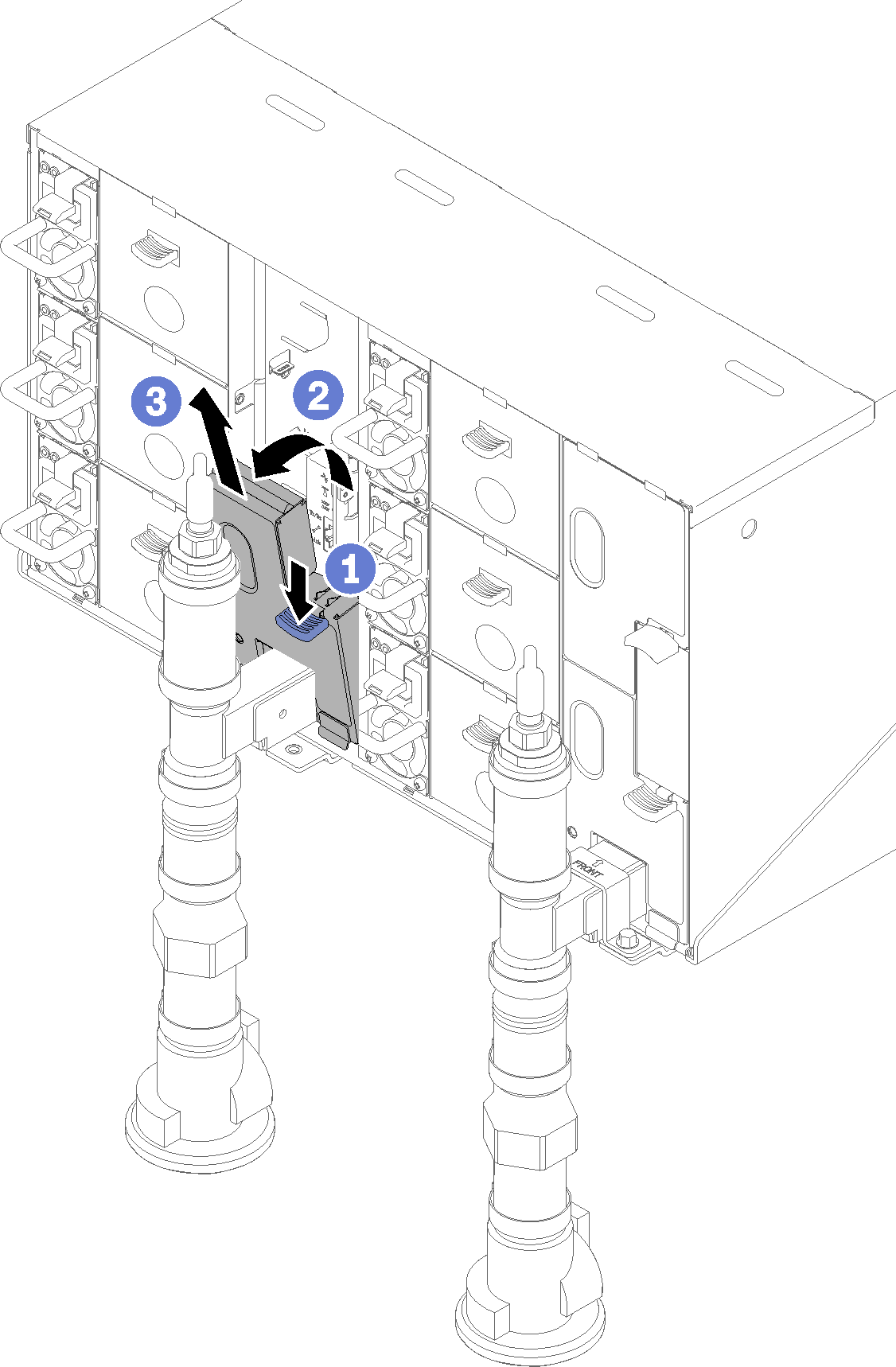
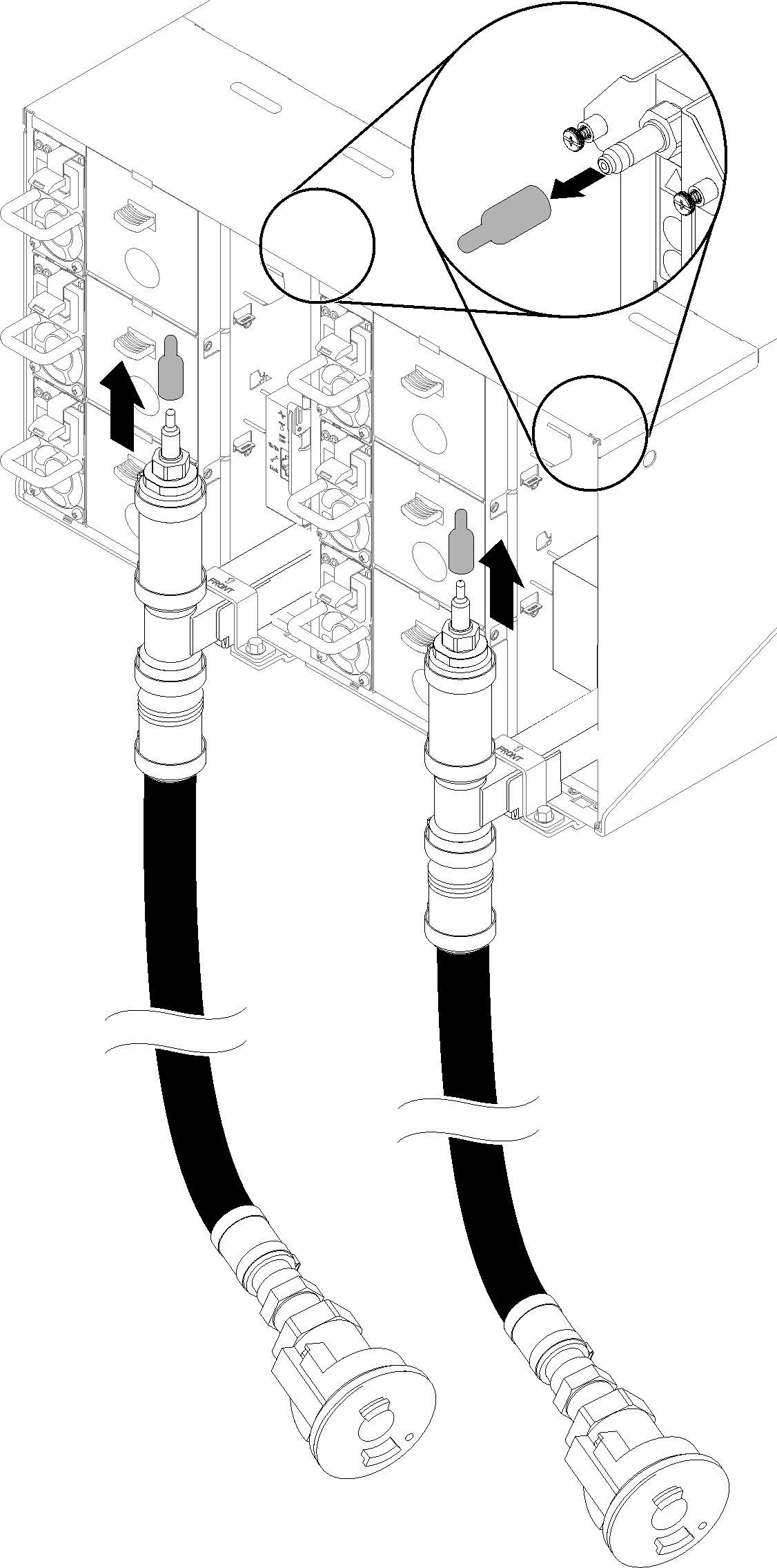
- Remove the red quick connect plug covers from the tops of each manifold.Figure 4. Quick connect plug covers removal
- Place the open blue hose end of the drain hose (tool left at customer site) into a bucket. Make sure that the lever on the drain hose valve is closed (lever is pointed away from the hose).Figure 5. Water draining
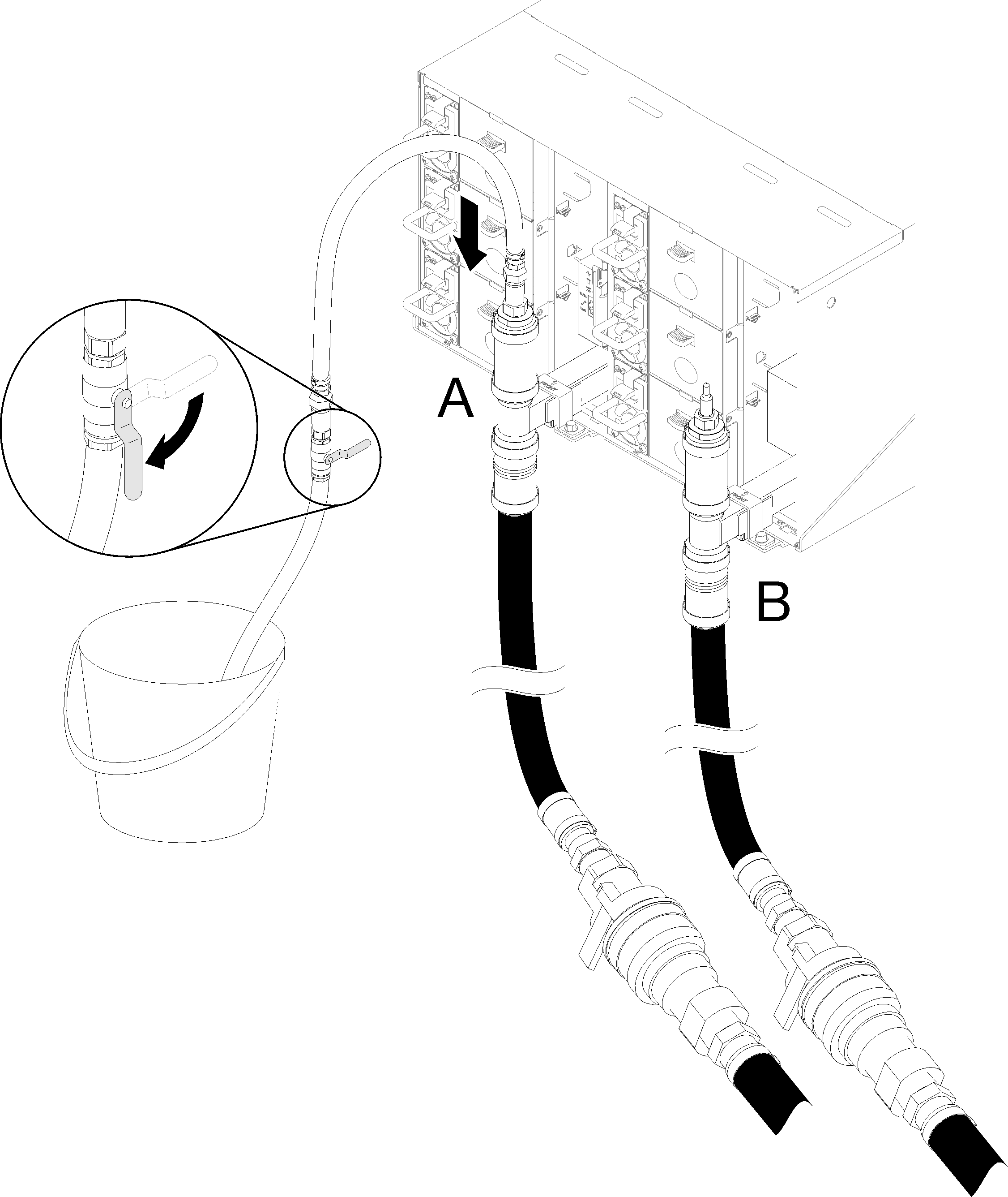
- Connect the Quick connect socket from the drain hose tool to the top of the return side manifold (position middle of the rack).Figure 6. Quick connect socket from the drain hose tool to the top of the return side manifold connection
- Once the quick connect is attached, slowly open the hose valve and allow water to drain until water stops flowing (approximately 1 minute).Figure 7. Water draining
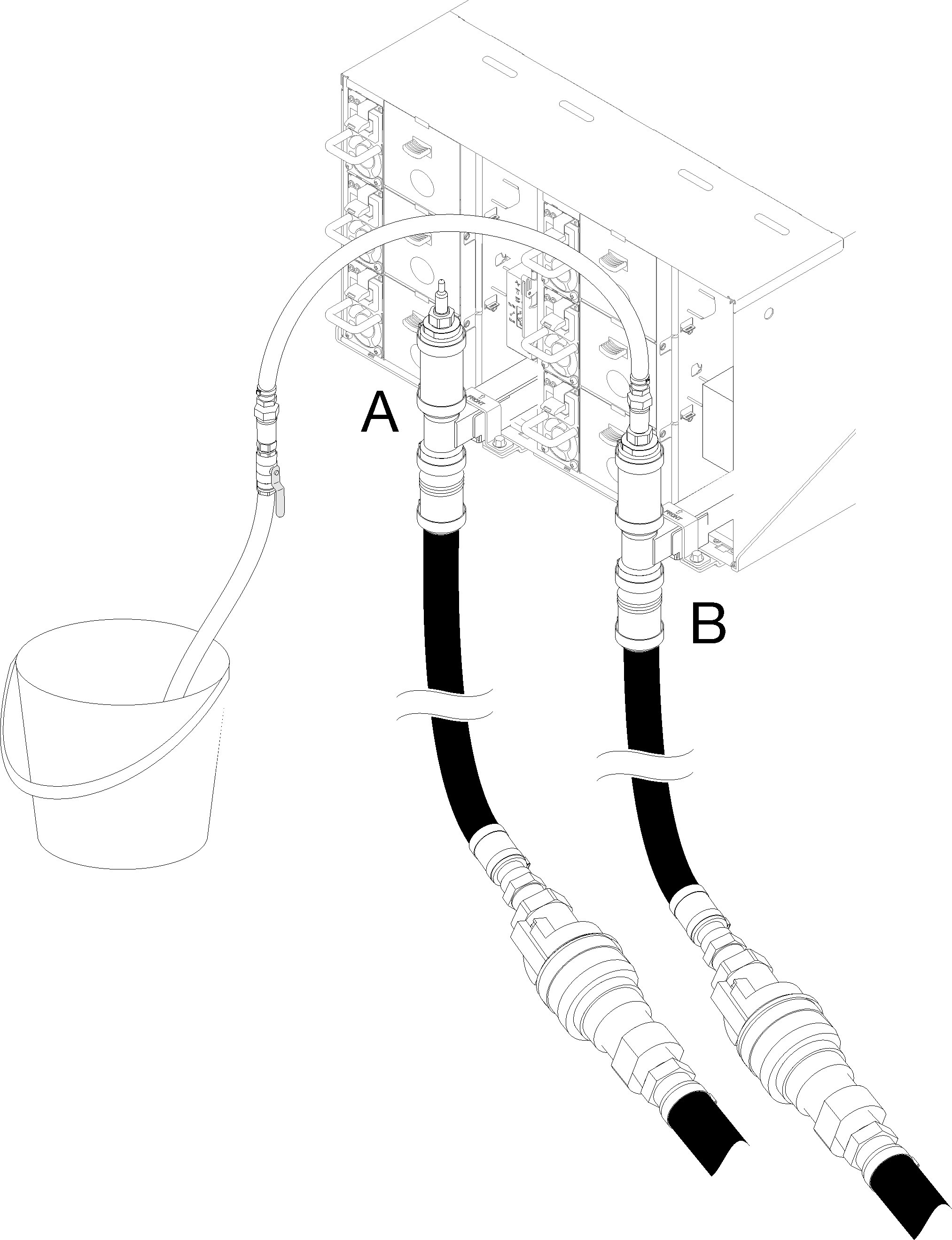
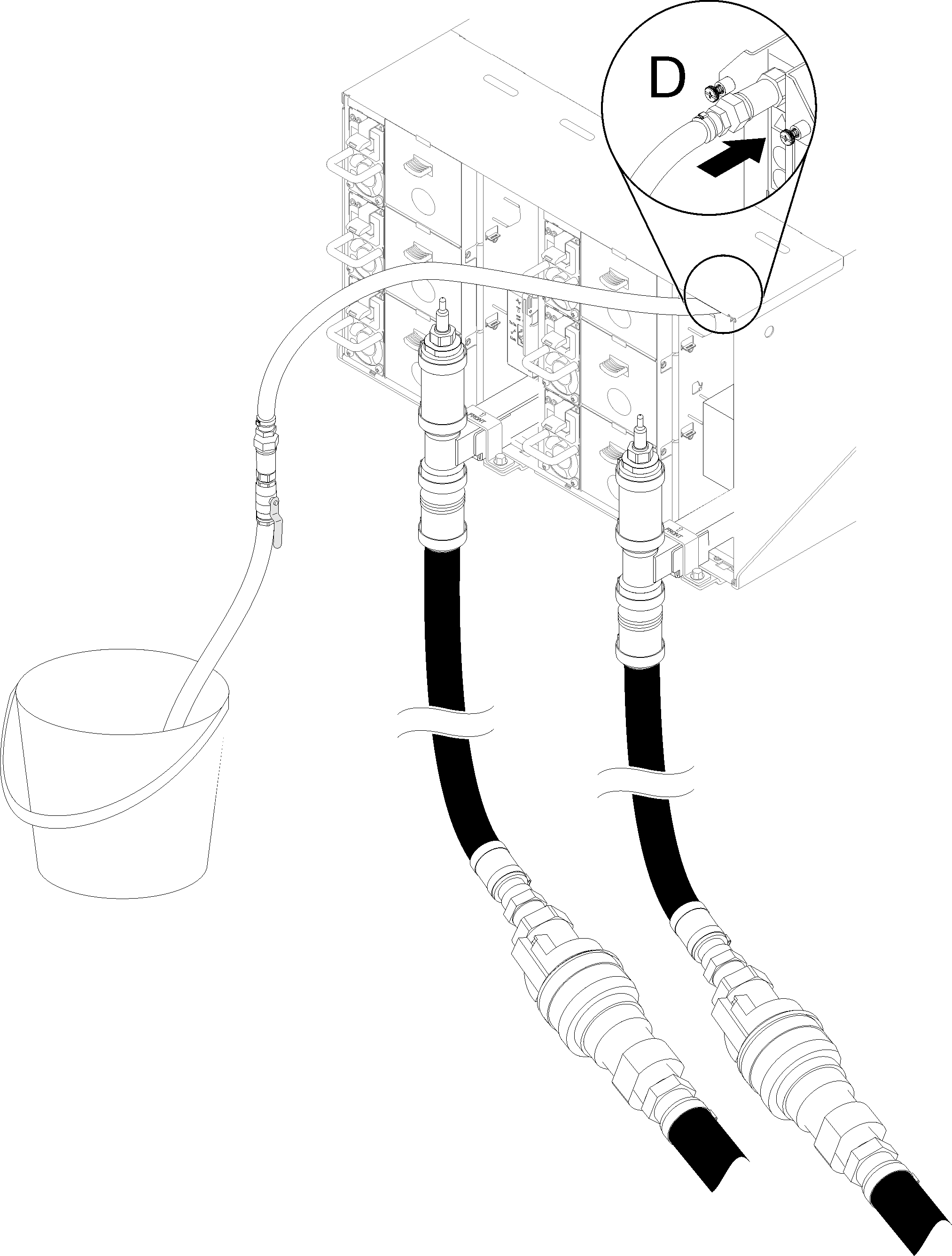
- Move to the top position of the other manifold (position closest to the rack side wall). Leave the hose connected to the top of the manifold until water stops flowing. Disconnect quick connect from top of manifold.Figure 8. Quick connect socket from the drain hose tool to the top of the supply side manifold connection
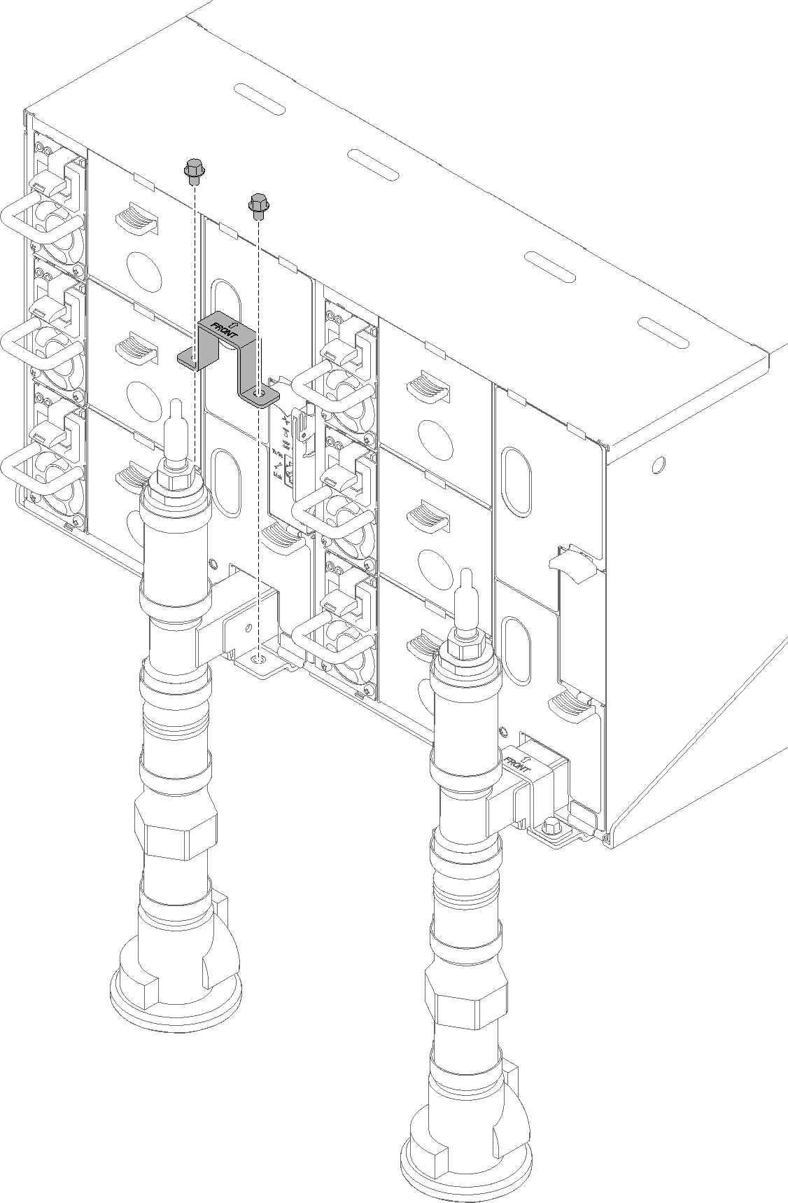
- Move to the rear of the rack. Remove manifold retention bracket that is retaining the manifold (top enclosure position only).Figure 9. Retention bracket removal
- Push the latch up upwards and slide the drip sensor assembly backwards, then; lift the drip sensor assembly up to clear sensor post and pull it out of the enclosure.Figure 10. Drip sensor assembly removal
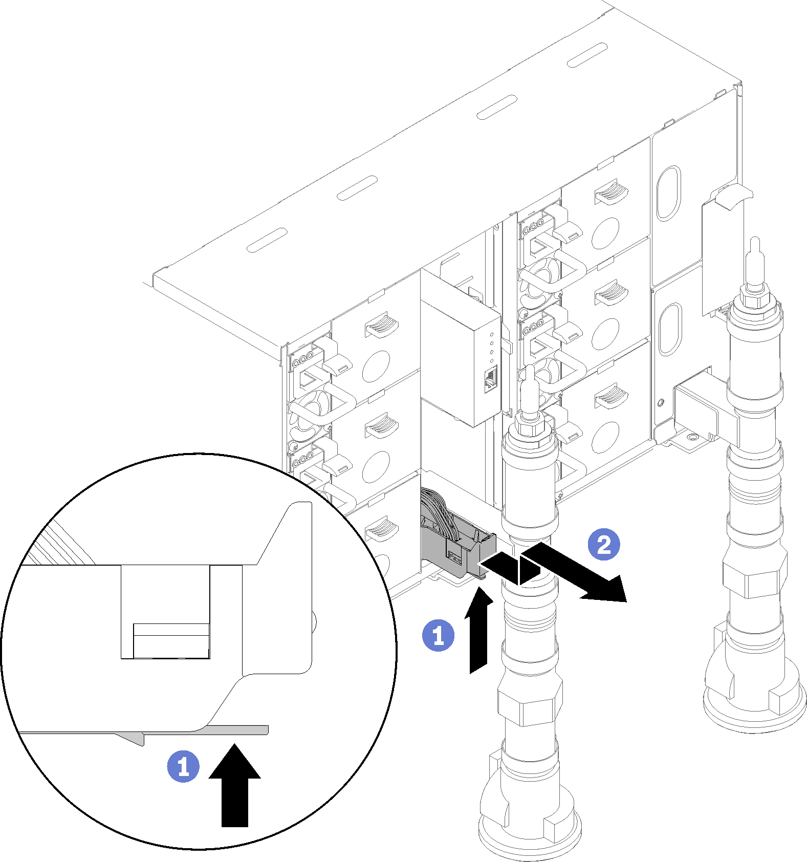 Figure 11. Drip sensor assembly
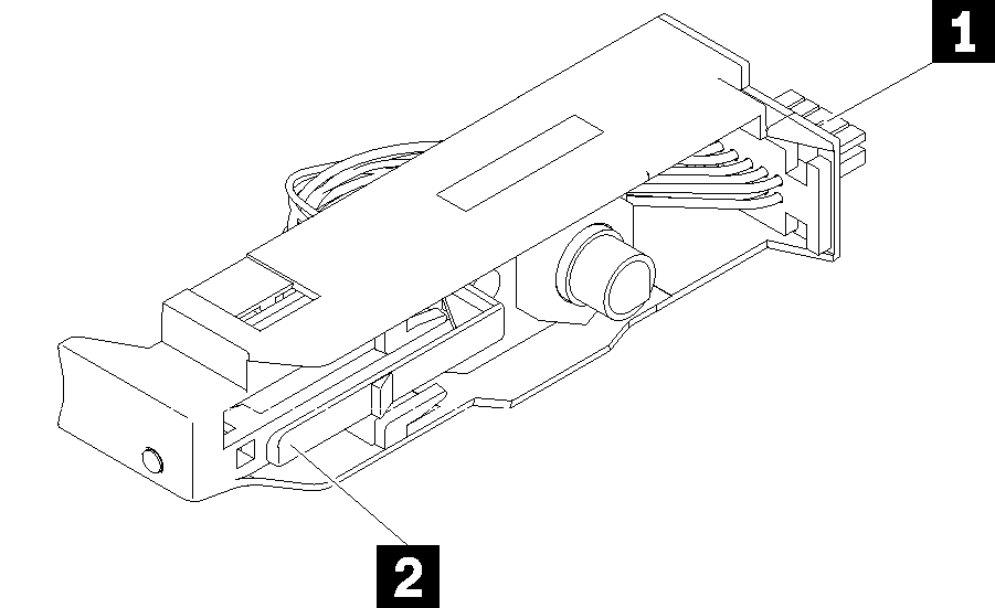
Table 2. Drip sensor assembly 1 Connector 2 Latch - Remove FPC card module and FPC card module support bracket if portion of left manifold is being replaced. If it is the right side manifold, remove blank filler.Figure 12. FPC card module removal
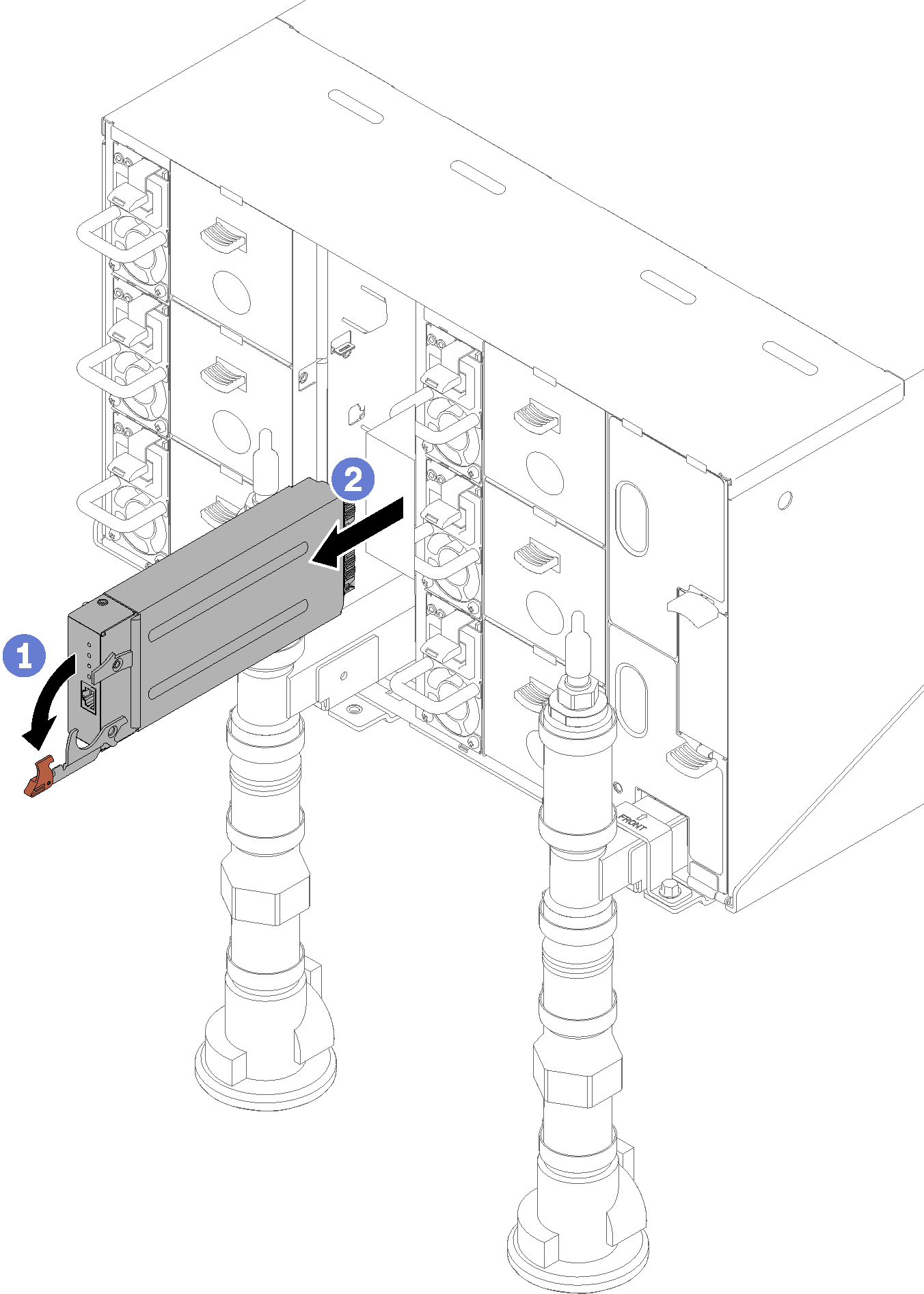 Figure 13. Support bracket removal
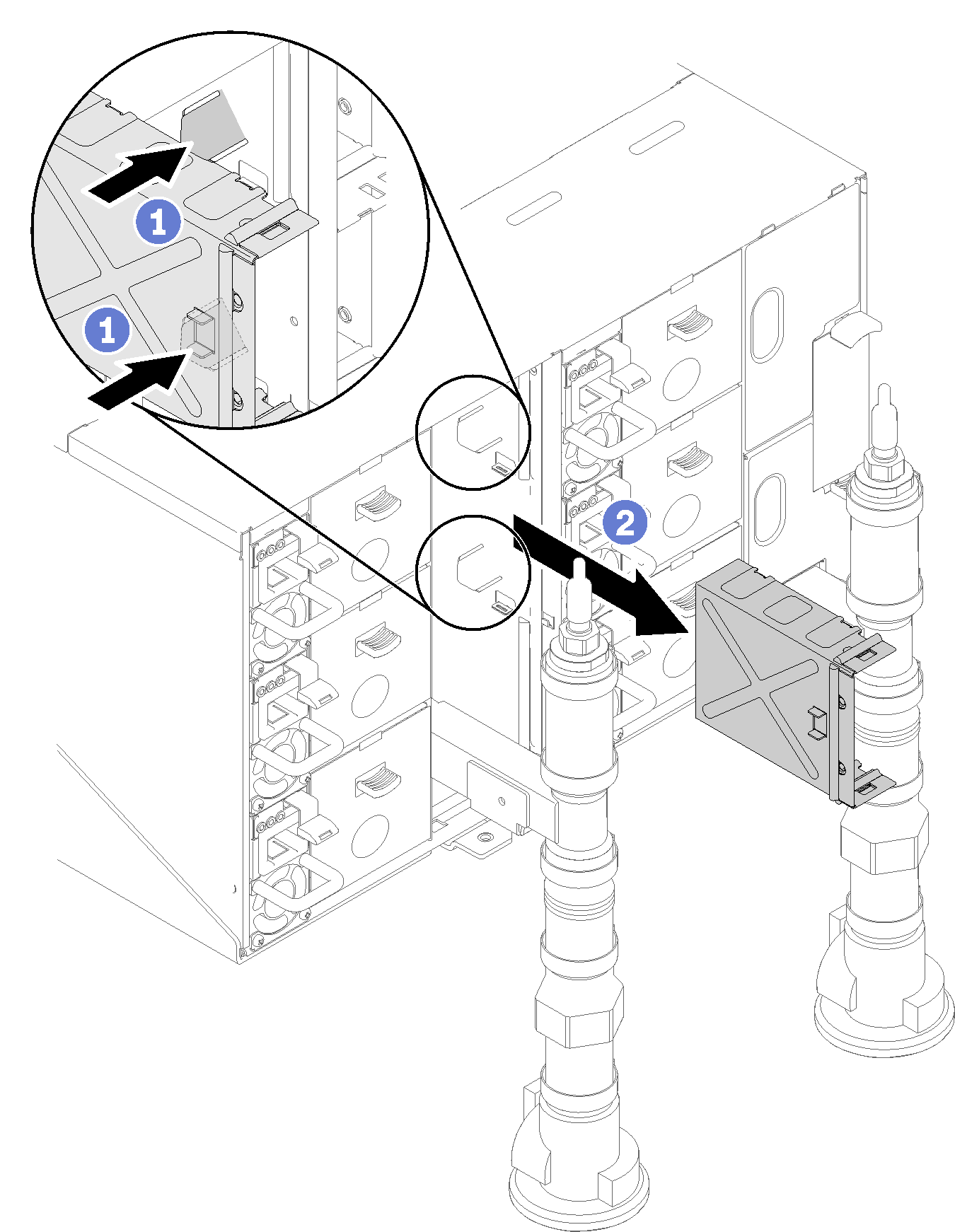
- Unscrew four screws (using the screwdriver contained in the manifold repair kit) to loosen the manifold bracket from the enclosure.Figure 14. Manifold screw locations
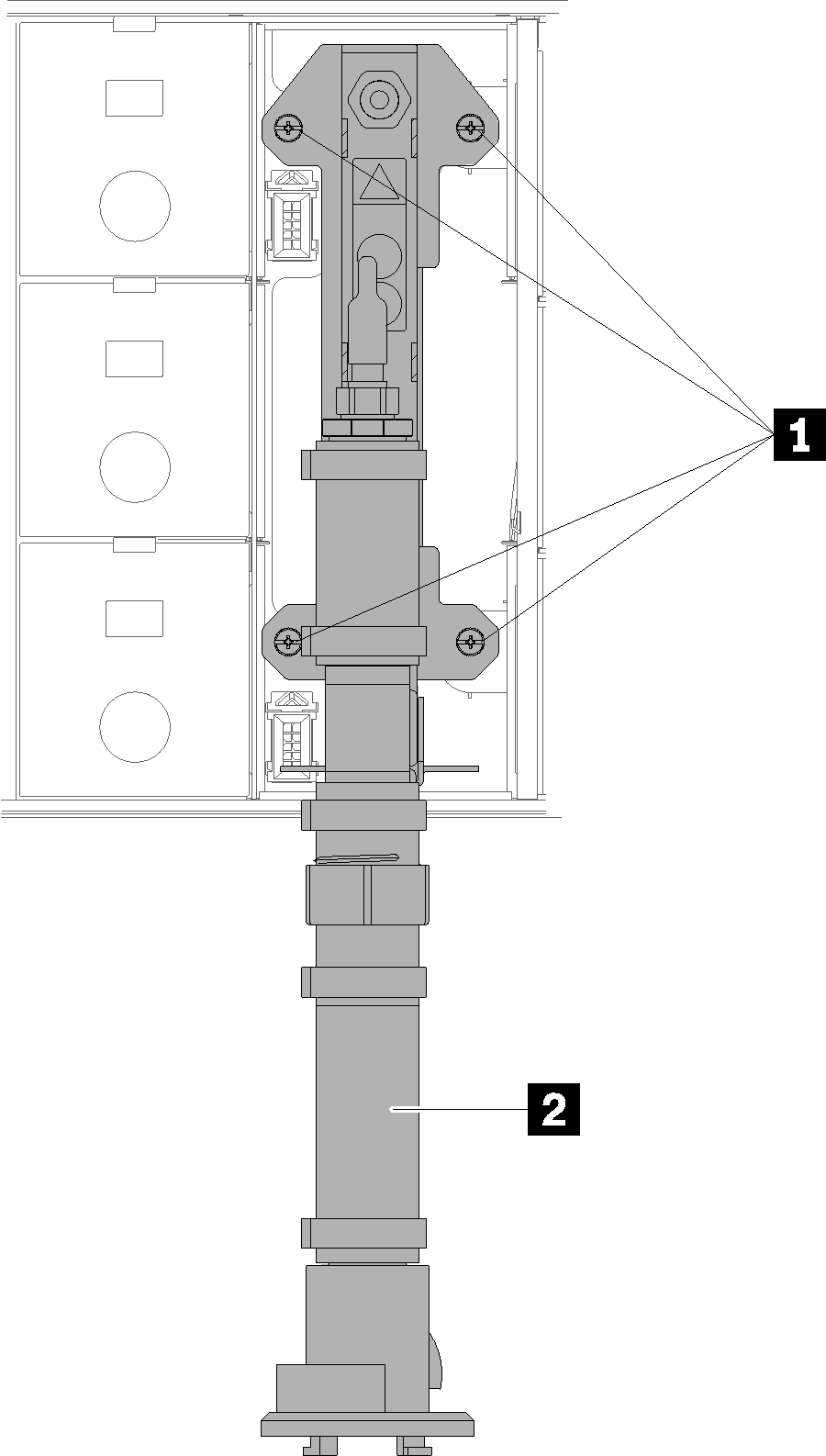
Table 3. Manifold screw locations 1 Screws 2 Manifold - Place a pan under the section of the manifold to be removed.Figure 15. Manifold disassemble
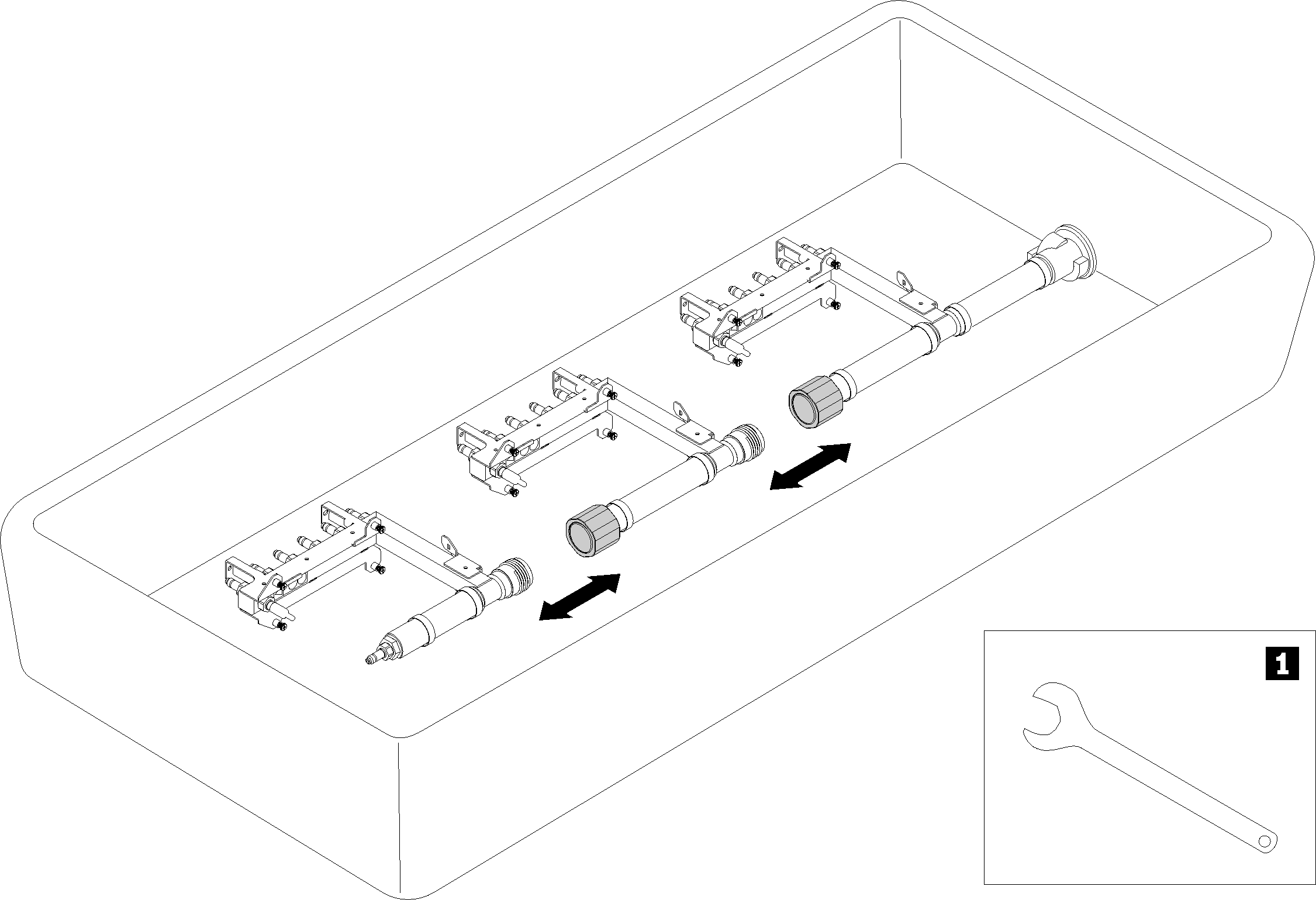
Table 4. Manifold disassemble 1 41mm wrench
If you are instructed to return the component or optional device, follow all packaging instructions, and use any packaging materials for shipping that are supplied to you.
Give documentation feedback