Internal cable routing
Use this information to route the cables for one-processor and two-processor configurations.
Disengage all latches, release tabs, or locks on cable connectors when you disconnect cables from the system board. Failing to release them before removing the cables will damage the cable sockets on the system board, which are fragile. Any damage to the cable sockets might require replacing the system board.
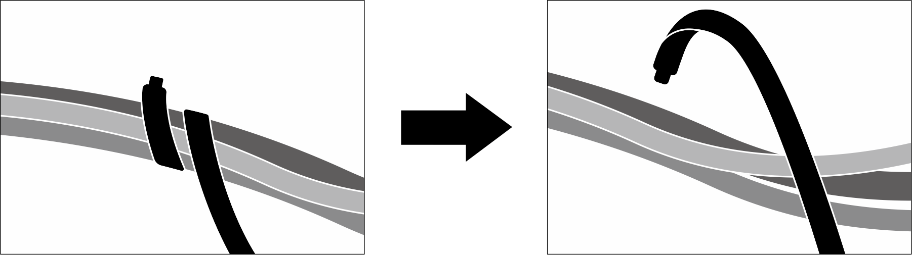
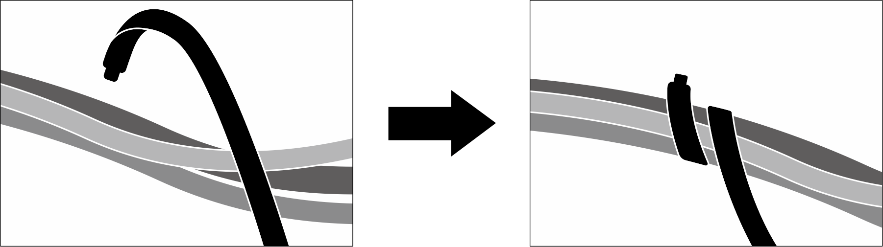
There are two cable ties on the GPU node. Unfasten the cable tie before removing the cables from the tray. After connecting the cables to the tray, bundle the cable tie to secure the cables.
Cable routing configurations
Follow the cable routing instruction below according the number of processors installed in the system.
One-processor configuration cable routing
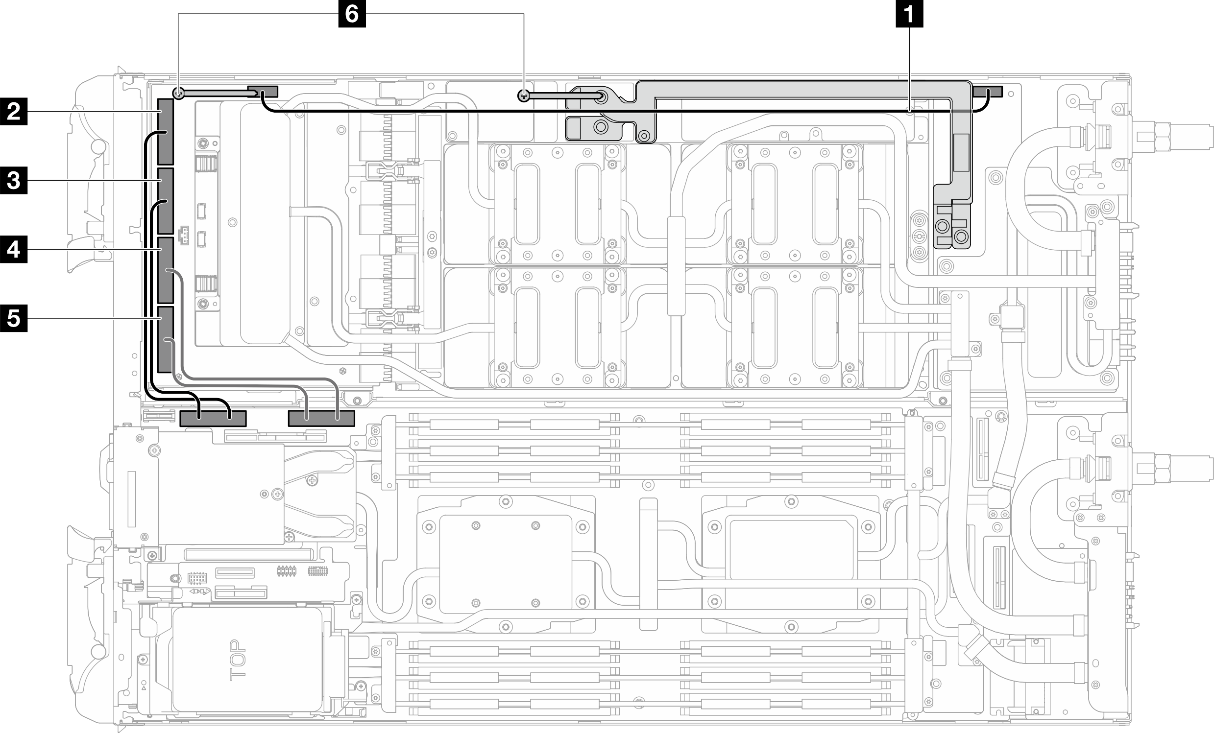
| Cable index | From (carrier board) | To |
|---|---|---|
| 1 | Power and side band connector | Power connector (on GPU node power distribution board) |
| 2 | MCIO 1 | PCIe 4 (on system board in compute node) |
| 3 | MCIO 2 | |
| 4 | MCIO 3 | PCIe 3 (on system board in compute node) |
| 5 | MCIO 4 | |
| 6 Cable tie | ||
Two-processor configuration cable routing
Follow the cable routing below for two-processor configuration.
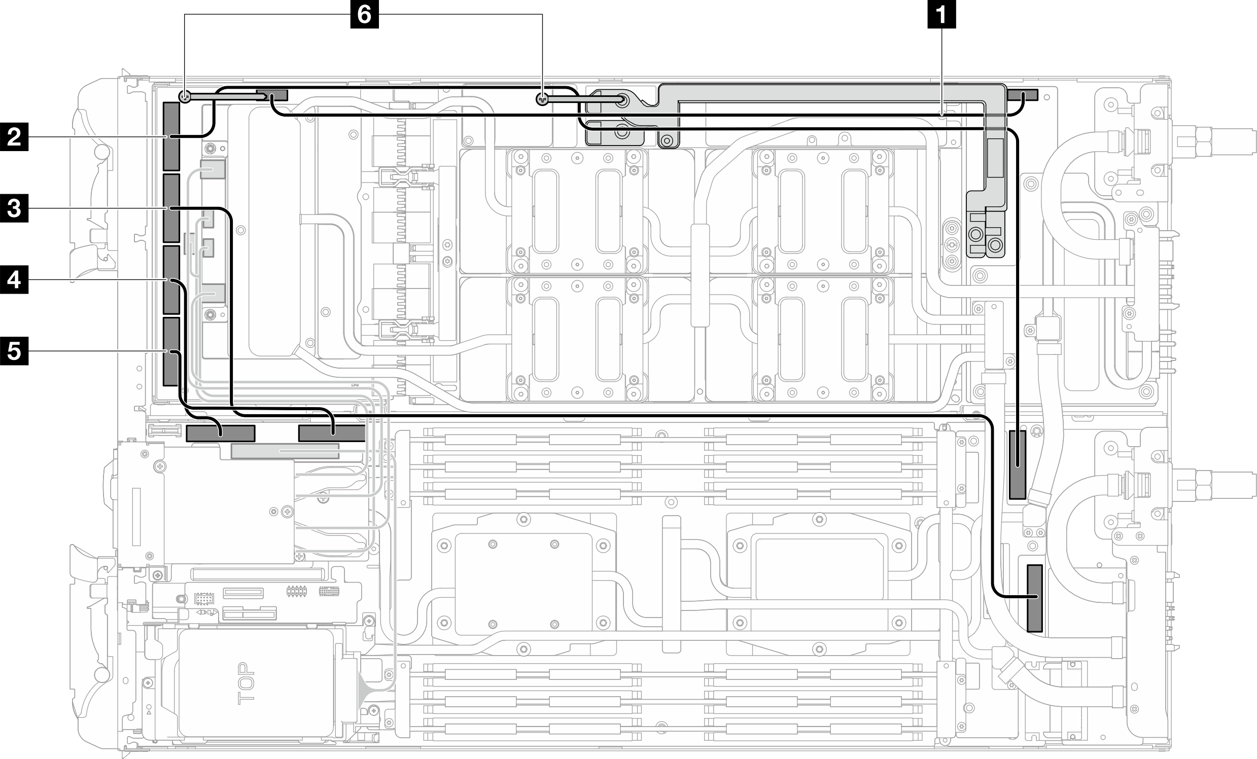
| Cable index | From (carrier board) | To |
|---|---|---|
| 1 | Power and side band connector | Power connector (on GPU node power distribution board) |
| 2 | MCIO 1 | PCIe 6 (on system board in compute node) |
| 3 | MCIO 2 | PCIe 5 (on system board in compute node) |
| 4 | MCIO 3 | PCIe 4 (on system board in compute node) |
| 5 | MCIO 4 | PCIe 3 (on system board in compute node) |
| 6 Cable tie | ||