Front view
The following illustration shows the controls, LEDs, and connectors on the front of the solution.
SD665 V3 tray contains two nodes; one left node and one right node (when viewed from front of enclosure). Both are compute nodes.
Up to six SD665 V3 trays can be installed in the DW612S 6U enclosure.
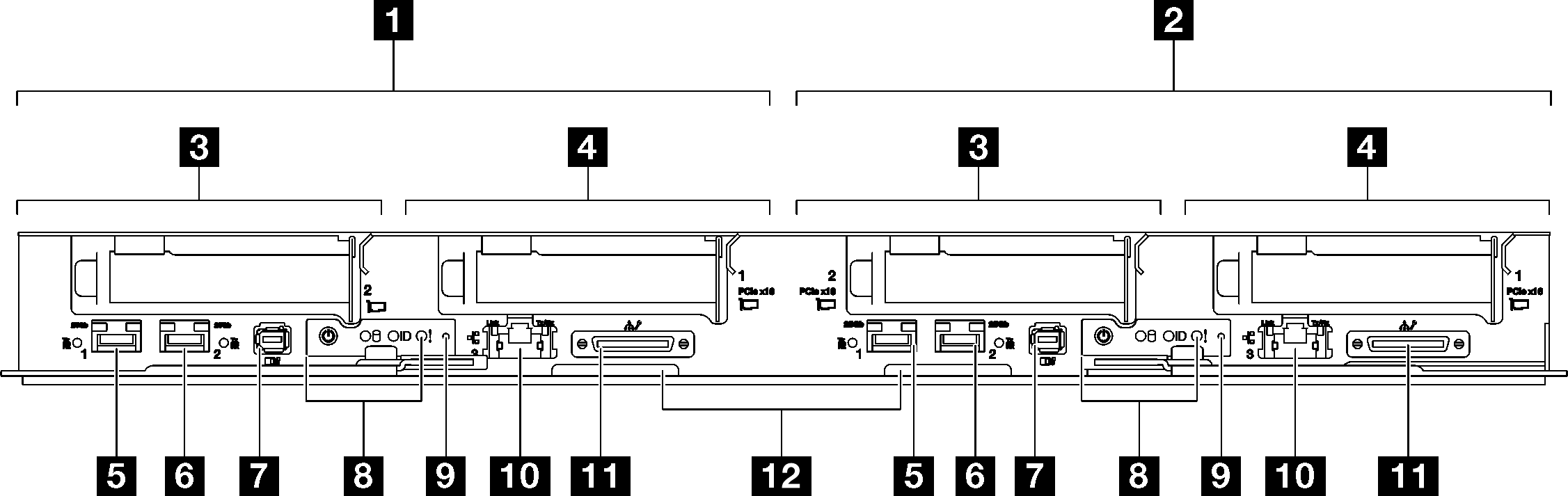
| 1 Compute node / Left node (odd bay numbers) | 7 External Diagnostics Handset connector. See External Diagnostics Handset for more information. |
| 2 Compute node / Right node (even bay numbers) | 8 Front operator panel LEDs. See Front LEDs. |
| 3 PCIe slot 2 or drive bay 2/3. See Hardware replacement procedures for component replacement. | 9 NMI button. Press this button to force a nonmaskable interrupt to the processor. You might have to use a pen or the end of a straightened paper clip to press the button. You can also use it to force a blue-screen memory dump. Use this button only when you are directed to do so by Lenovo Support. |
| 4PCIe slot 1 or drive bay 0/1. See Hardware replacement procedures for component replacement. | 10 1 Gb RJ45 Ethernet port with share-NIC feature for Lenovo XClarity Controller. See Front LEDs for more information. Lenovo XClarity Controller connection is mutually exclusive between RJ45 Ethernet connector and 25Gb SFP28 Port 1. |
| 5 25 Gb SFP28 Ethernet port (Port 1) with share-NIC feature for Lenovo XClarity Controller. See Front LEDs for more information. Lenovo XClarity Controller connection is mutually exclusive between RJ45 Ethernet connector and 25Gb SFP28 Port 1. | 11 KVM breakout cable connector The KVM breakout cable includes VGA connector, serial port connector, and USB 3.0 (5 Gbps) / 2.0 connector. XCC mobile management is supported by USB connector on the KVM breakout cable. |
| 6 25 Gb SFP28 Ethernet port (Port 2). See Front LEDs for more information. | 12 Pull-out information tab with Lenovo XClarity Controller network access label. See Identify the solution and access the Lenovo XClarity Controller for more information. |