Cable routing for the hot-swap drives
Follow instructions in this section to learn how to do cable routing for the 15mm and 7mm 2.5-inch hot-swap drives.
Identifying connectors on the drive backplanes
The following illustration shows the connectors on the drive backplanes that are used for internal cable routing.
Figure 1. Connectors for cable routing on Drive backplane 1 (lower) 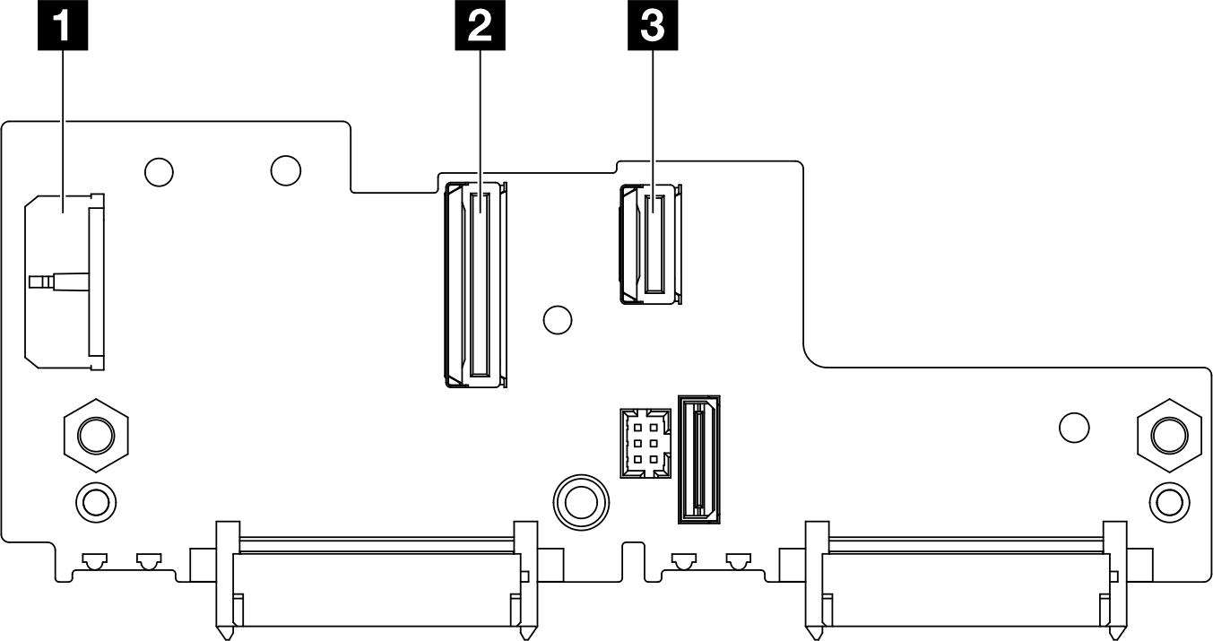 | Figure 2. Connector for cable routing on Drive backplane 2 (upper) 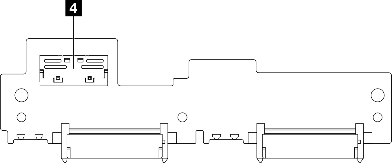 |
| 1 Drive-backplane 1 power connector | 3 Drive-backplane 1 MCIOx4 connector for SATA |
| 2 Drive-backplane 1 MCIO connector for NVMe | 4 Drive-backplane 2 MCIO connector for NVMe |
15mm NVMe drives
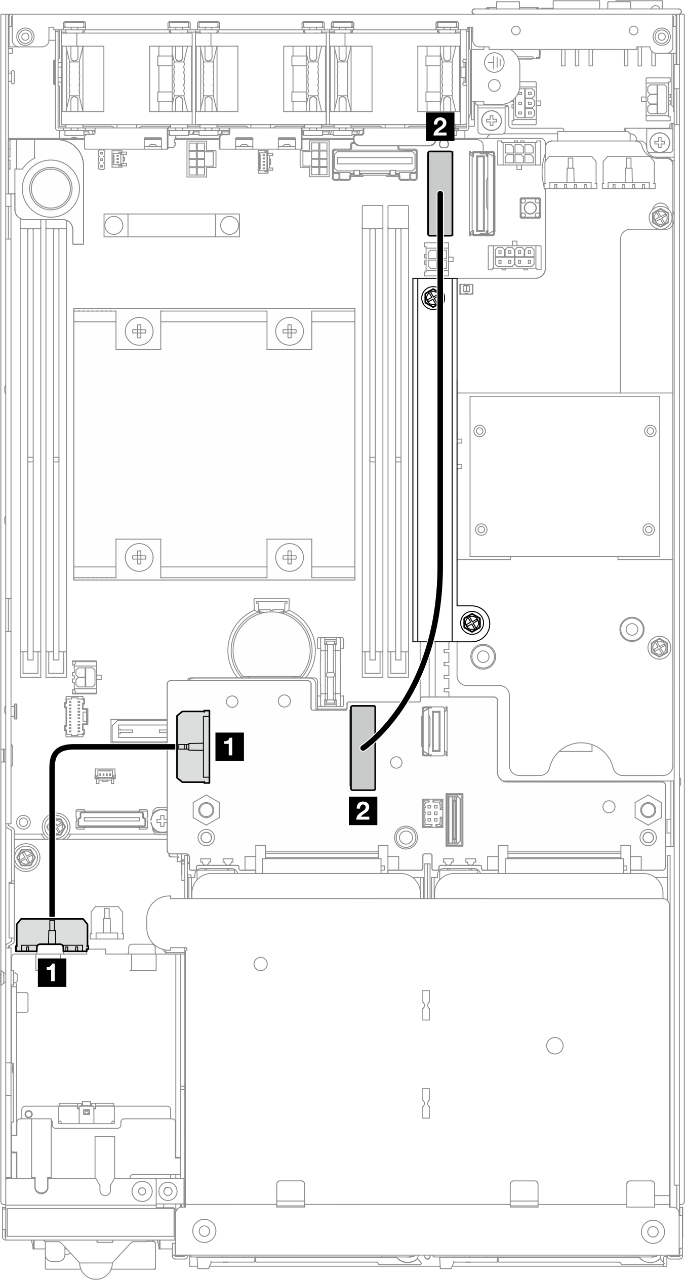
| From | To | Cable length |
|---|---|---|
| 1 Drive-backplane 1 power connector | 1 Power connector for drive backplane on the I/O module board | 85 mm |
| 2 Drive-backplane 1 MCIO connector for NVMe | 2 MCIO connector 1 on the system board | 250 mm |
Make sure that all cables between the drive backplane(s) and the system-board connectors go through the cable wall on the power module board.
For a better result of cable routing, install the cable of the keylock switch before connecting the drive-backplane power cable (1) (see Install a keylock switch with cable).
7mm SATA drives
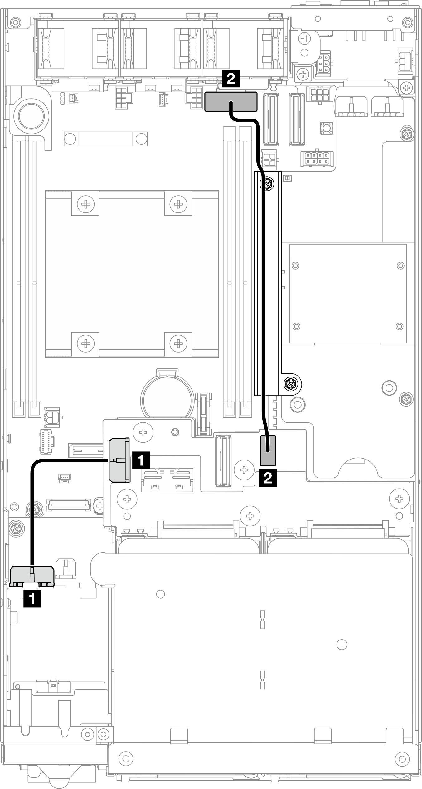
| From | To | Cable length |
|---|---|---|
| 1 Drive-backplane 1 power connector | 1 Power connector for drive backplane on the I/O module board | 85 mm |
| 2 Drive-backplane 1 MCIOx4 connector for SATA | 2 SATA connector on the system board | 220 mm |
Make sure that all cables between the drive backplane(s) and the system-board connectors go through the cable wall on the power module board.
For a better result of cable routing, install the cable of the keylock switch before connecting the drive-backplane power cable (1) (see Install a keylock switch with cable).
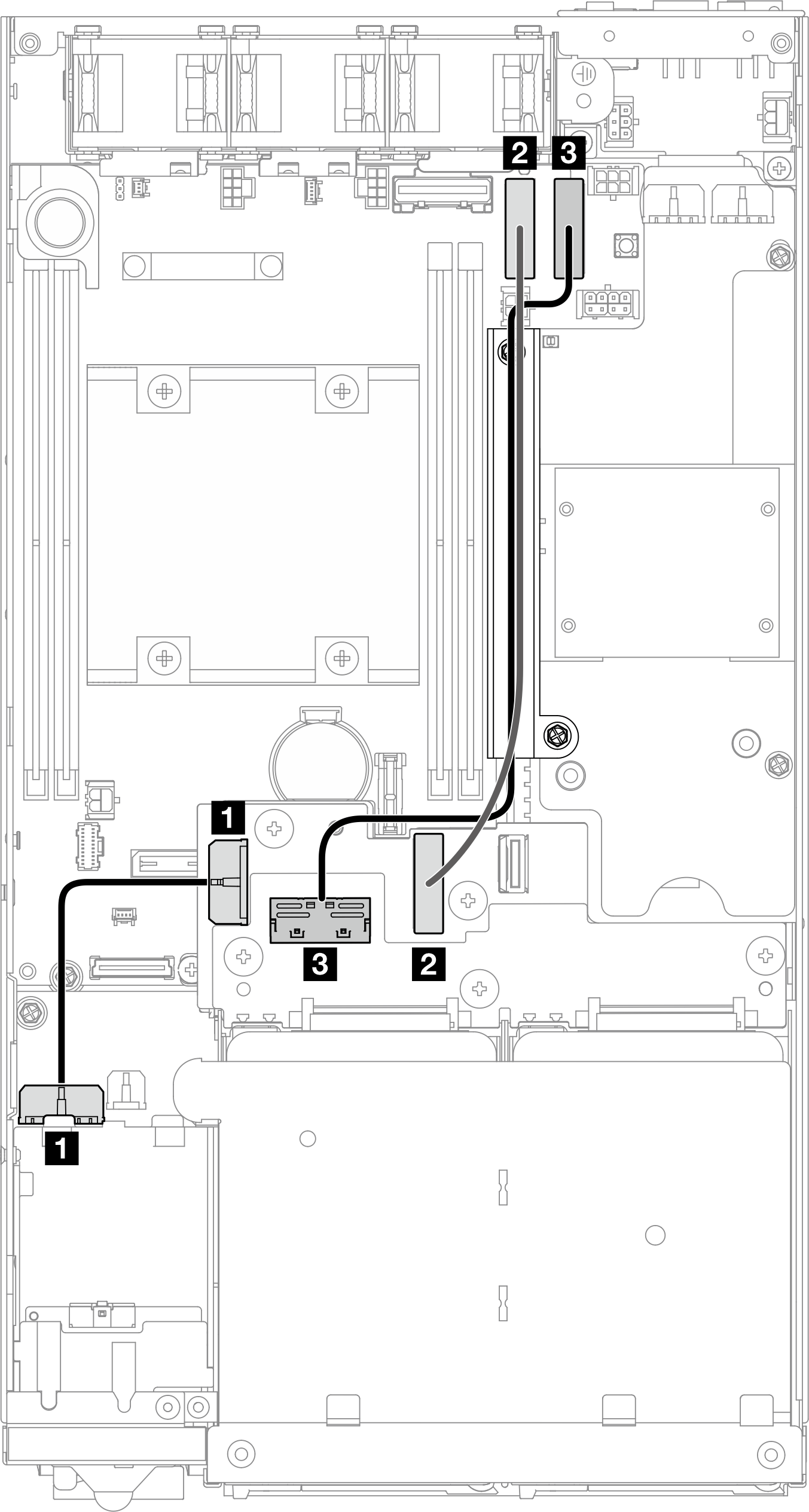
7mm NVMe drives
| From | To | Cable length |
|---|---|---|
| 1 Drive-backplane 1 power connector | 1 Power connector for drive backplane on the I/O module board | 85 mm |
| 2 Drive-backplane 1 MCIO connector for NVMe | 2 MCIO connector 1 on the system board | 250 mm |
| 3 Drive-backplane 2 MCIO connector for NVMe | 3 MCIO connector 2 on the system board | 300 mm |
Make sure that all cables between the drive backplane(s) and the system-board connectors go through the cable wall on the power module board.
For a better result of cable routing, install the cable of the keylock switch before connecting the drive-backplane power cable (1) (see Install a keylock switch with cable).