Cable routing for the power module board and power input board module
Follow instructions in this section to learn how to do cable routing for the power input board (PIB) module and power module board (PMB).
For a smooth installation, connect the cables between the power module board and power input board module BEFORE installing the power module board.
- Depending on the specific configuration, the components in the node might be one of the following. The appearances are different but the procedure is almost the same.
- DC PMB and DC PIB
- Internal power supply (AC PMB) and AC PIB

| Cable | From (Power module board) | To (Power input board) |
|---|---|---|
| 1 | LED connector | PMB status LED |
| 2 & 3 | Two power connectors Important
| Two power connectors |
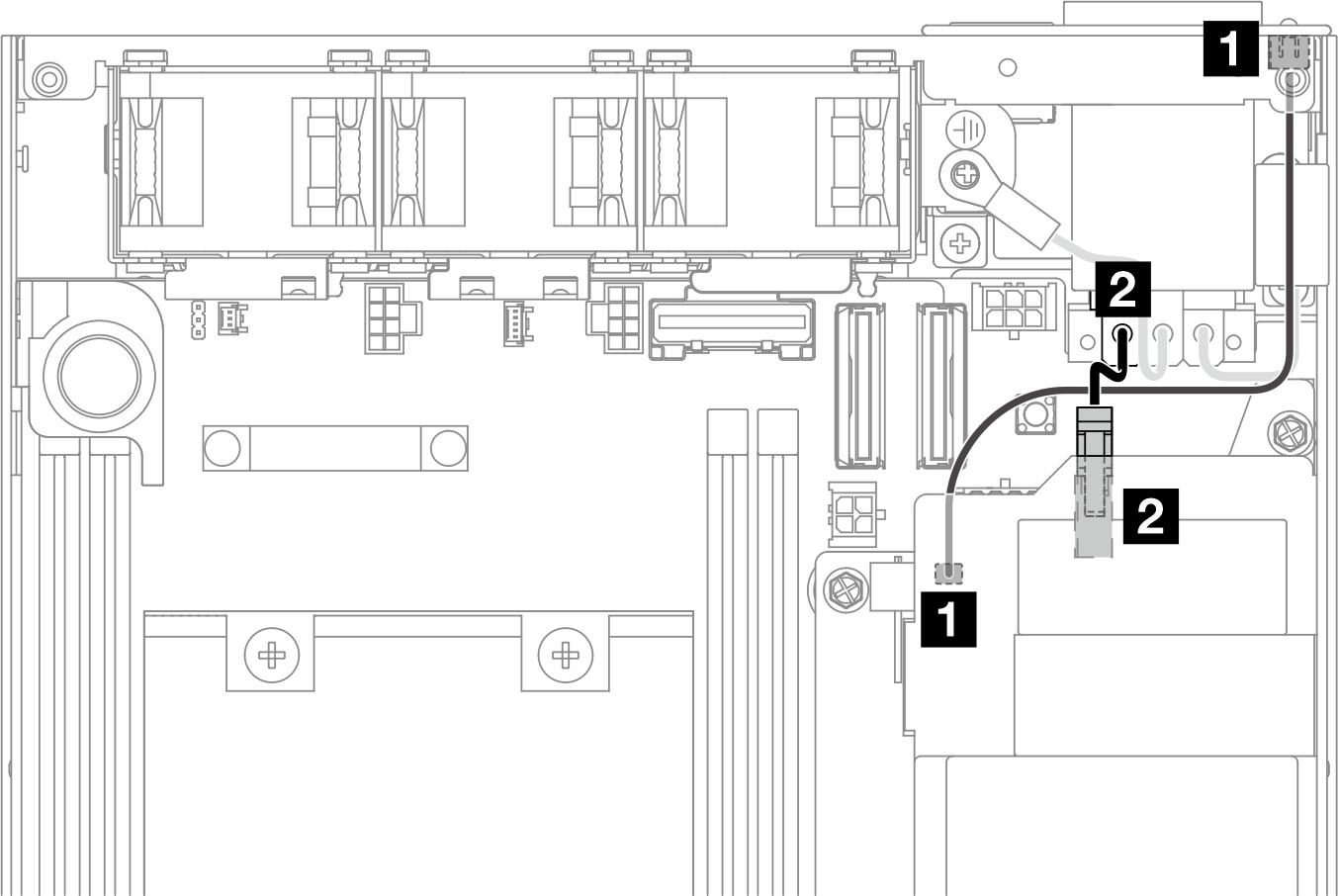
| Cable | From (AC PMB) | To (AC PIB) |
|---|---|---|
| 1 | LED connector | PMB status LED |
| 2 | Power connector | Attached power cable |
Procedure of installing the PMB-PIB cables
- Depending on the configuration, connect and organize the two or three cables (1, 2, 3) for the power input board module and power module board.
 Connect the PMB status LED cable (1) to the power module board.
To disconnect the power cable(s), first remove the power module board (see Remove the power module board (PMB)).
The LED latch is fragile; removing the PMB status LED cable from the PIB module is highly likely to break the latch. Remove this cable from the PIB module only when it is absolutely necessary.