Install a power input board (PIB) module
Follow instructions in this section to install a power input board (PIB) module.
About this task
To avoid potential danger, make sure to read and follow the safety information.
- S002
 CAUTIONThe power-control button on the device and the power switch on the power supply do not turn off the electrical current supplied to the device. The device also might have more than one power cord. To remove all electrical current from the device, ensure that all power cords are disconnected from the power source.
Attention
Read Installation Guidelines and Safety inspection checklist to make sure that you work safely.
Touch the static-protective package that contains the component to any unpainted metal surface on the node; then, remove it from the package and place it on a static-protective surface.
- Depending on the specific configuration, proceed to the corresponding section for the procedure of the DC PIB module or AC PIB module.
Install a DC PIB module
Procedure
- Make preparations for this task.
- Install the PIB module to the node.
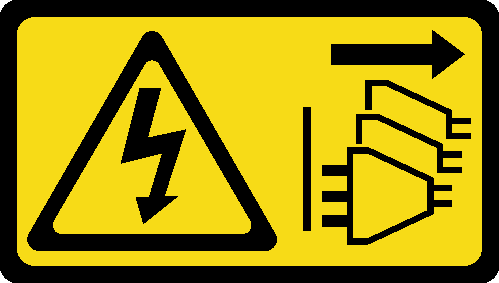
 Align the power input board module with its slot; then, carefully insert the power input board module into place.Note
Use the exterior side and rear-top side of the power input board module as the touch points.
- When inserting the power input board module into place, make sure to connect it to the connector on the system board.
 Tighten the four screws as shown.Figure 1. Installation of the DC PIB module
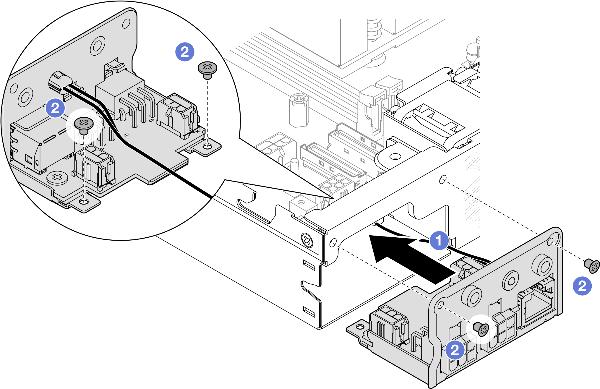
After this task is completed
- Proceed to connect the cable(s) between the power input board module and the power module board; then, install the power module board (see Install a power module board (PMB) and Cable routing for the power module board and power input board module).
- Proceed to complete the parts replacement (see Complete the parts replacement).
Install an AC PIB module
Procedure
- Make preparations for this task.
- Install the PIB module to the node.
- Align the power input board module with its slot; then, carefully insert the power input board module into place.Note
- When inserting the power input board module into place, make sure to connect it to the connector on the system board.
- Tighten the four screws as shown.Figure 2. Installation of the AC PIB module
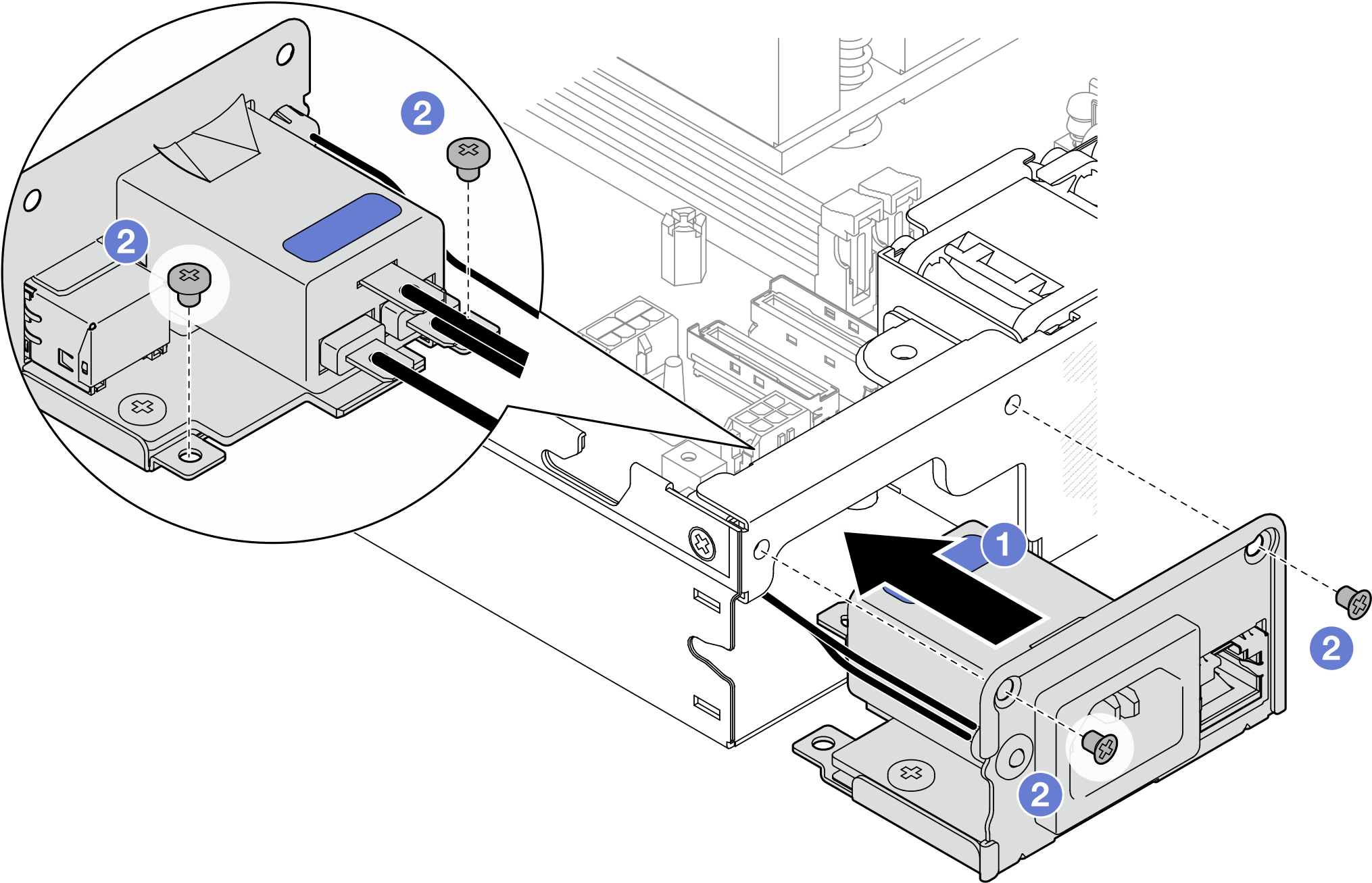
 Place the PIB ground wire onto the screw hole on the rear edge of the node; then, tighten the screw to secure the ground wire.
 Insert the X-cap between the PIB module and the node sidewall.Figure 3. Installation of the AC PIB ground wire and X-cap
After this task is completed
- Proceed to connect the cables between AC PIB module and the internal power supply unit; then, install the internal power supply unit (see Install an internal power supply unit (AC PMB) and Cable routing for the power module board and power input board module).
- Proceed to complete the parts replacement (see Complete the parts replacement).
Give documentation feedback