Install an internal power supply unit (AC PMB)
Follow instructions in this section to install an internal power supply unit (AC PMB).
About this task
To avoid potential danger, make sure to read and follow the safety information.
- S002
 CAUTIONThe power-control button on the device and the power switch on the power supply do not turn off the electrical current supplied to the device. The device also might have more than one power cord. To remove all electrical current from the device, ensure that all power cords are disconnected from the power source.
Attention
Read Installation Guidelines and Safety inspection checklist to make sure that you work safely.
Touch the static-protective package that contains the component to any unpainted metal surface on the node; then, remove it from the package and place it on a static-protective surface.
Procedure
- Install the internal power supply unit and the cable wall.
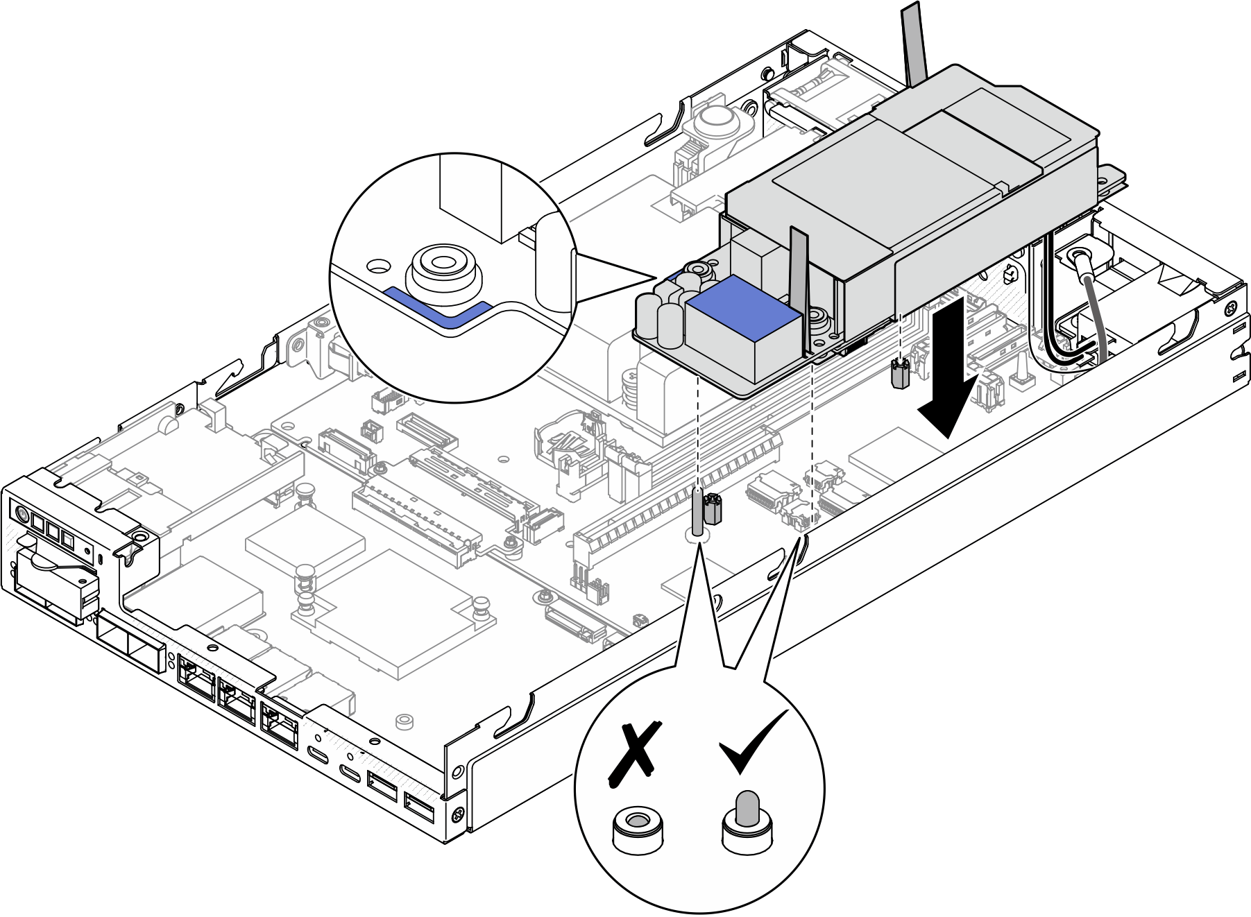
- Align the internal power supply unit with the guide pins, lower and insert the internal power supply unit into place, and slightly press the touch point until it is securely seated.ImportantMake sure that the busbars are seated in the holes of the internal power supply unit as shown in the illustration.Figure 1. Installation of the internal power supply unit
- For easier operation, bundle the X-cap cables and the PIB ground wire with a cable strap if necessary.Figure 2. Bundling the cables
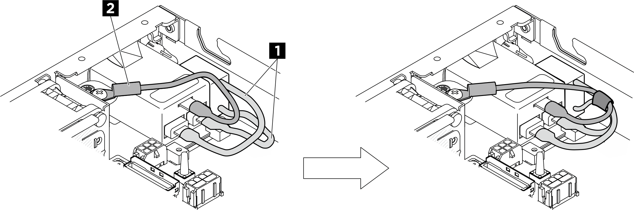
1 X-cap cables 2 PIB ground wire  Tighten the two screws by the sidewall of the node.
 Lower the cable wall into place on the internal power supply unit; then, tighten the two screws.ImportantMake sure to place the pull tape beneath the cable wall as shown in the illustration to keep the pull tape away from the DIMM slots. Otherwise, it may interfere with the memory modules and cause system failure.Figure 3. Installation of the cable wall and the internal power supply unit
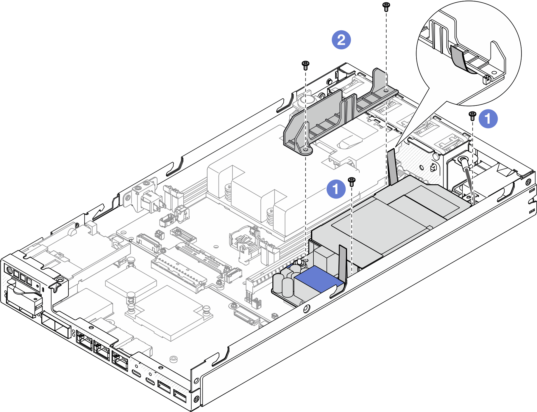
- Align the internal power supply unit with the guide pins, lower and insert the internal power supply unit into place, and slightly press the touch point until it is securely seated.
After this task is completed
- Reinstall the drive cage and reconnect the required drive cables (see Install a drive cage and Cable routing for the hot-swap drives).
- Proceed to complete the parts replacement (see Complete the parts replacement).
Give documentation feedback