Top view
This section contains the components visible from the top of the server.
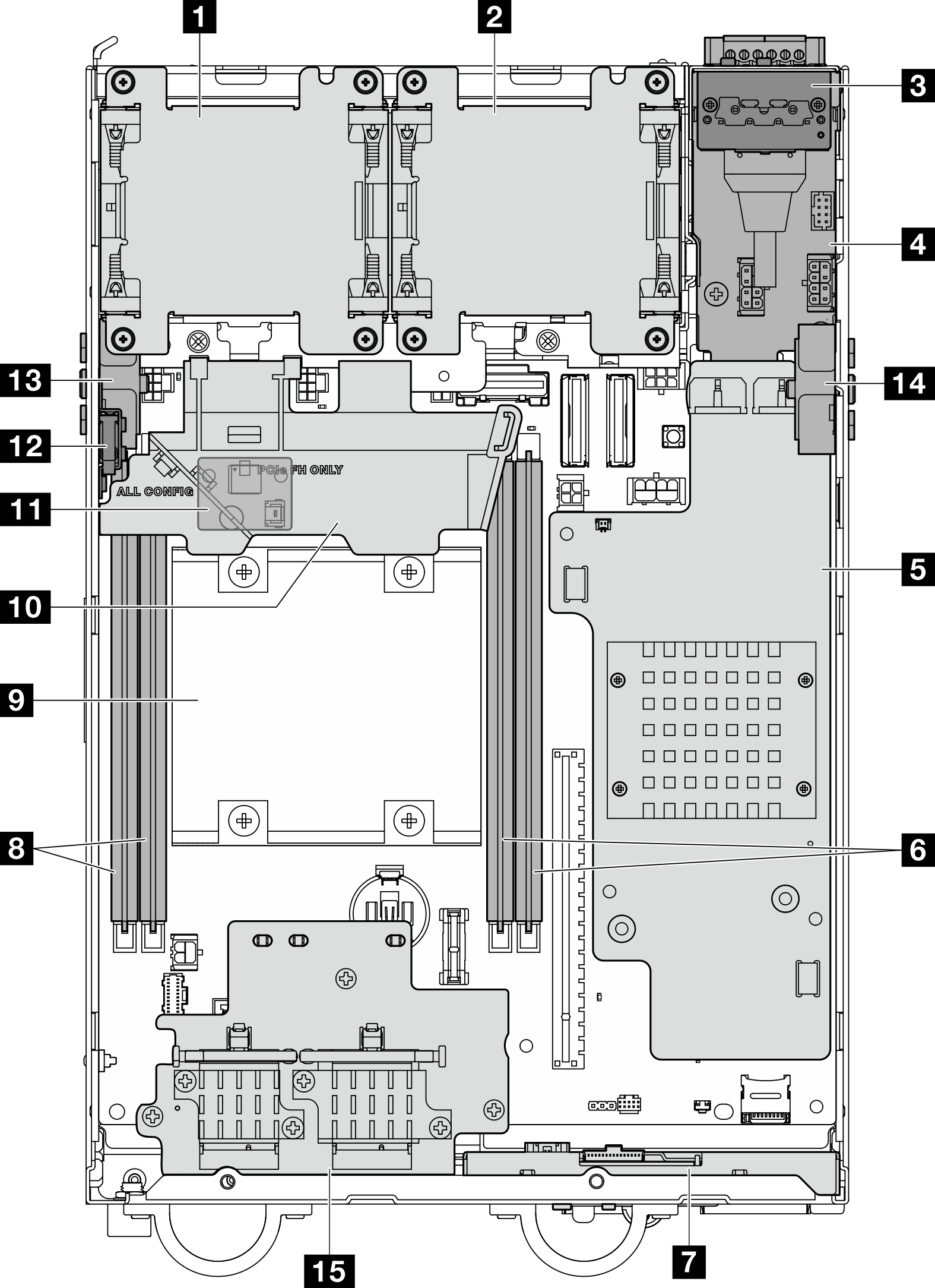
Figure 1. Top view
Note
Depending on the model, your server might look slightly different from the illustration.
| 1 Fan 1 | 9 Processor |
| 2 Fan 2 | 10 Processor air baffle |
| 3 Rear operator panel | 11 Air flow sensor board (on the bottom side of processor air baffle) (Optional) |
| 4 Power input board (PIB) module | 12 Top intrusion switch |
| 5 DC power module board (DC PMB) or internal power supply unit (AC PMB) | 13 Processor side SMA assembly or SMA filler |
| 6 DIMM slot 3 and 4 | 14 PMB side SMA assembly or SMA filler |
| 7 Front operator panel | 15 Wireless adapter (Optional) |
| 8 DIMM slot 1 and 2 |
Give documentation feedback