Disassemble the system board for recycle
Follow the instructions in this section to disassemble the system board before recycling.
About this task
Read Safety inspection checklist and Installation Guidelines to ensure that you work safely.
Power off the corresponding compute node that you are going to perform the task on.
Remove the compute node from the chassis. See Remove the compute node from chassis.
Carefully lay the compute node on a flat, static-protective surface, orienting the compute node with the bezel pointing toward you.
Make sure you have T8 Torx, T10 Torx, Phillips #1, and hex socket drivers available.
Refer to local environmental, waste or disposal regulations to ensure compliance.
Procedure
- Remove the screws from the bottom side of the chassis.
- Using a T10 Torx screwdriver and a Phillips #1 screwdriver, remove the screws from the bottom side of the chassis. Remove the I/O expansion adapter retention clips away from the system board.Figure 1. Compute node positioning direction
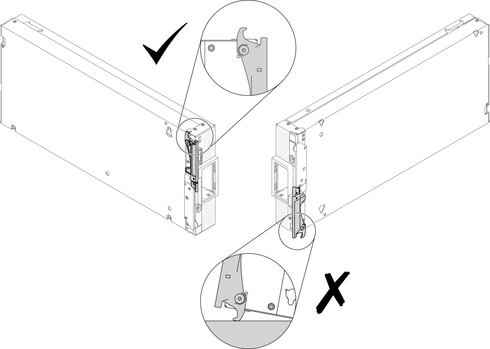 Figure 2. Screws removal from bottom side of the chassis
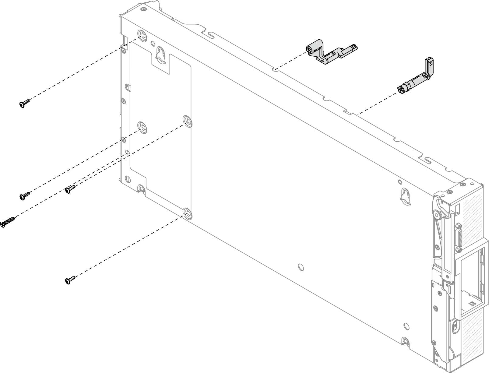
- Using a T10 Torx screwdriver and a Phillips #1 screwdriver, remove the screws from the bottom side of the chassis. Remove the I/O expansion adapter retention clips away from the system board.
- Remove the bulkhead.
- Carefully place the compute node to the up-side-down orientation.
- Using a T8 Torx screwdriver, remove the five screws securing the bulkhead.
- Remove the bulkhead from the compute node.
Figure 3. Bulkhead removal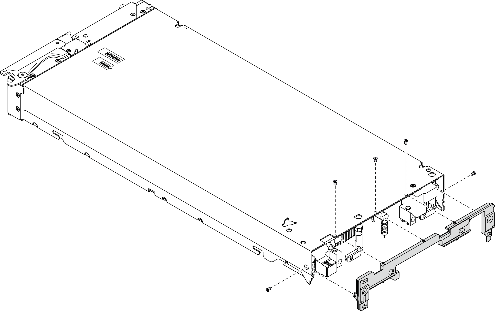
- Remove the front panel.
- Using a hex socket driver, remove the fasteners securing the KVM connector.Figure 4. Unfastening front panel screws
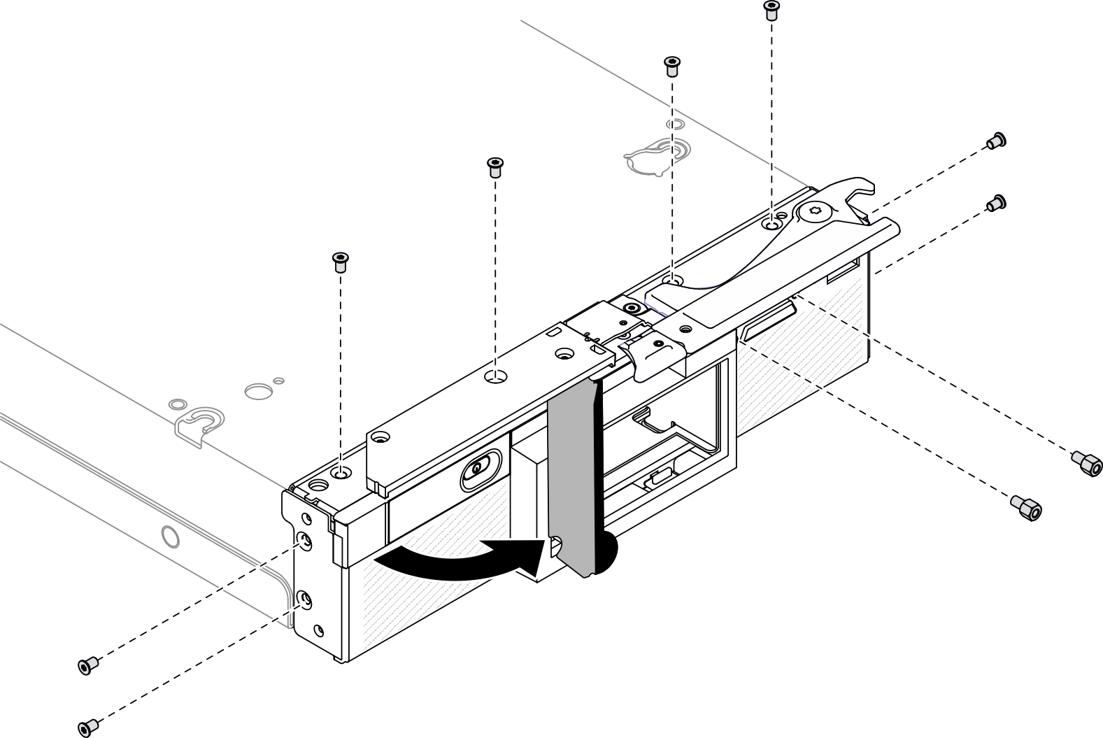
- Carefully place the compute node to the bottom-side-down orientation, remove the front panel from the compute node.Figure 5. Removing the front panel
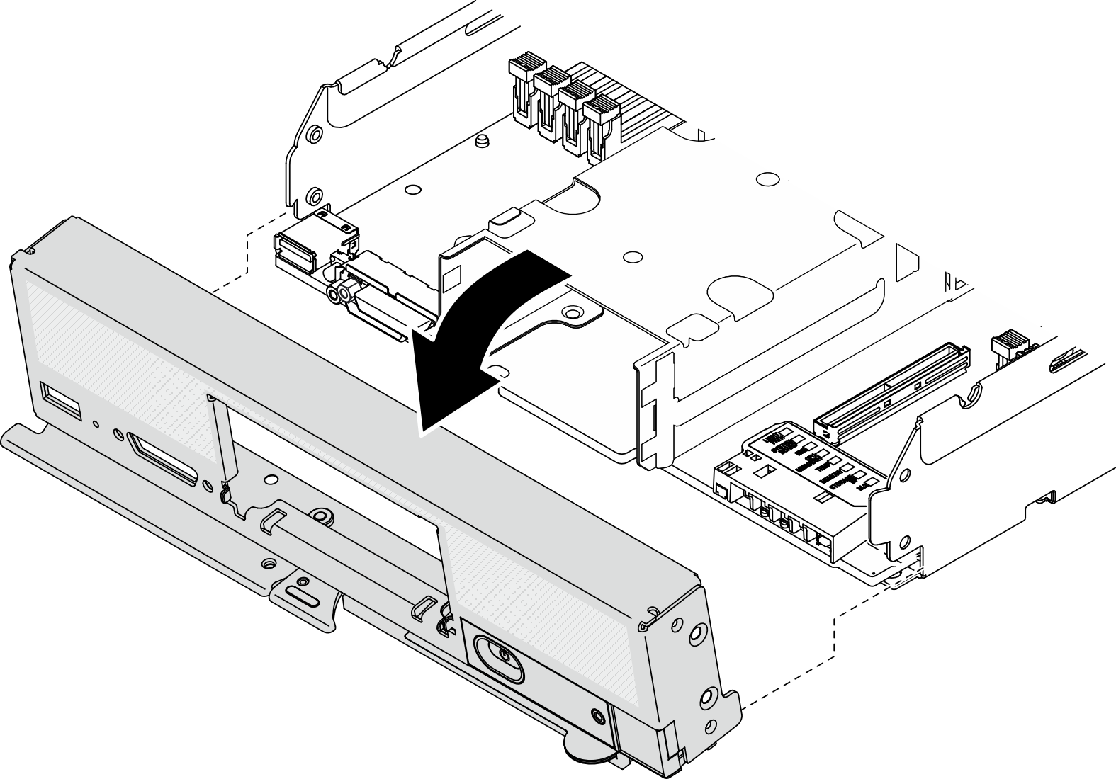
- Using a hex socket driver, remove the fasteners securing the KVM connector.
- Remove the hot-swap drive cage.
- Remove the cage from the compute node.Figure 6. Hot-swap drive cage removal
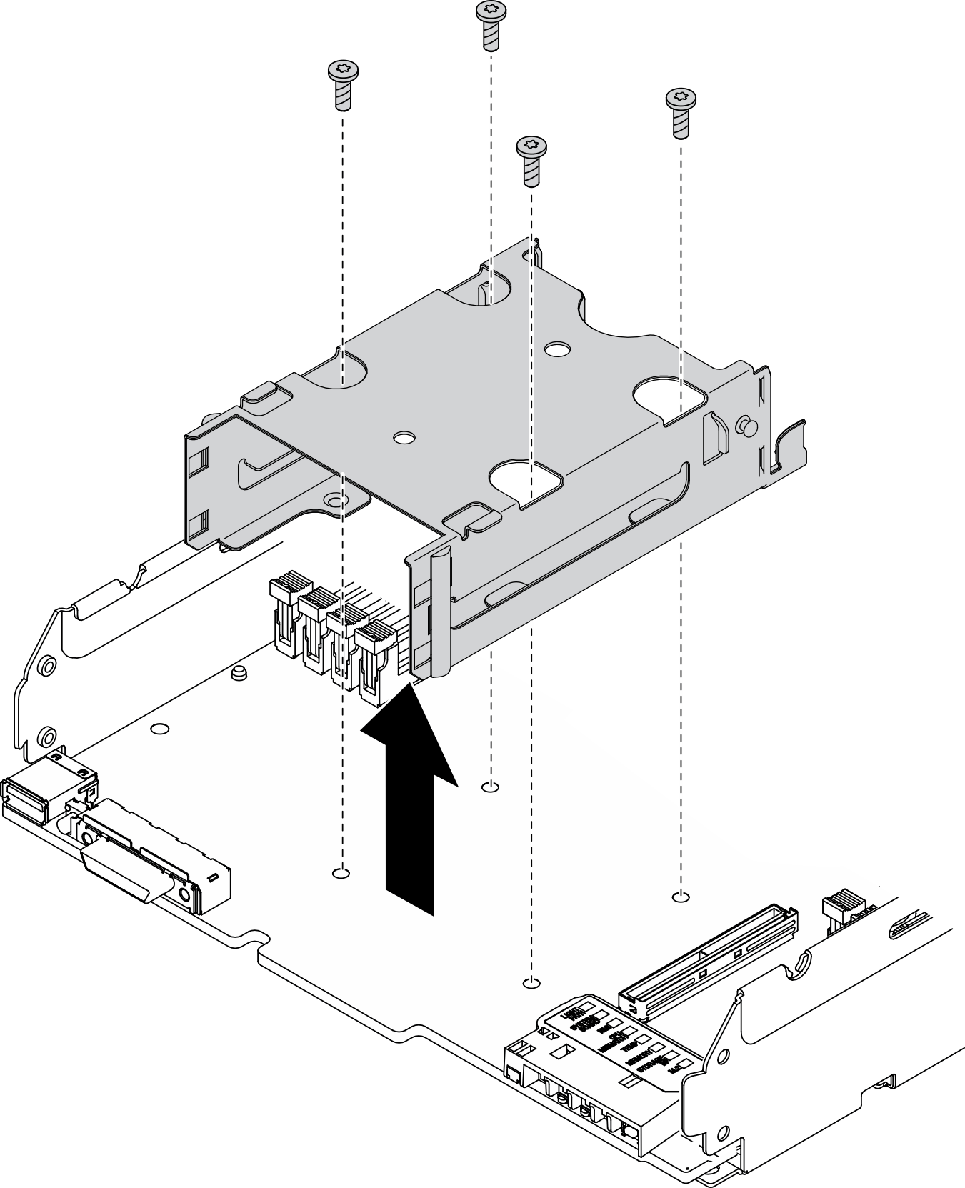
- Remove the cage from the compute node.
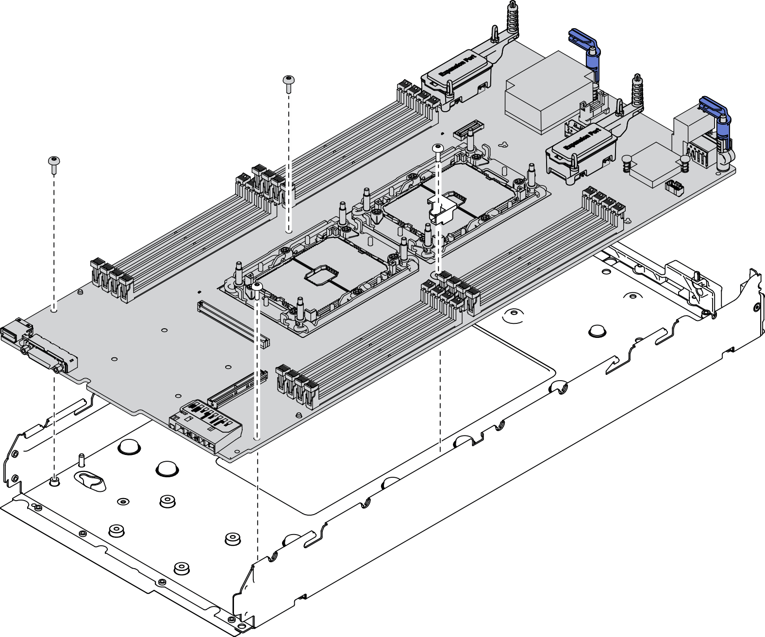
- Remove the four screws securing system board to the chassis, and remove the processor key from the system board. Then, lift up the system board from the chassis.Figure 7. Removing the system board
After disassembling the compute node, recycle the unit in compliance with local regulations.