Remove a memory module
Use this information to remove a memory module.
About this task
Read Safety inspection checklist and Installation Guidelines to ensure that you work safely.
Power off the corresponding compute node that you are going to perform the task on.
Remove the compute node from the chassis. See Remove the compute node from chassis.
Carefully lay the compute node on a flat, static-protective surface, orienting the compute node with the bezel pointing toward you.
If you are not installing a replacement memory module to the same slot, make sure you have memory module filler available.
- Memory modules are sensitive to static discharge and require special handling. Refer to the standard guidelines for Handling static-sensitive devices.
Always wear an electrostatic-discharge strap when removing or installing memory modules. Electrostatic-discharge gloves can also be used.
Never hold two or more memory modules together so that they do not touch each other. Do not stack memory modules directly on top of each other during storage.
Never touch the gold memory module connector contacts or allow these contacts to touch the outside of the memory module connector housing.
Handle memory modules with care: never bend, twist, or drop a memory module.
Do not use any metal tools (such as jigs or clamps) to handle the memory modules, because the rigid metals may damage the memory modules.
Do not insert memory modules while holding packages or passive components, which can cause package cracks or detachment of passive components by the high insertion force.
After you install or remove a memory module, you must change and save the new configuration information by using the Setup utility. When you turn on the compute node, a message indicates that the memory configuration has changed. Start the Setup utility and select Save Settings to save changes. (see the Lenovo ThinkSystem SN550 V2 Type 7Z69 Setup Guide for more information.)
Procedure
- Remove the memory module from the slot.
 Carefully use a common tool to press the retaining clips.
 Push the retaining clips outward on each end of the memory module slot.
 Grasp the memory module at both ends and carefully lift it out of the slot.
AttentionRemove or install memory modules for one processor at a time.
To avoid breaking the retaining clips or damaging the memory module slots, handle the clips gently.
NoteThe retaining clips for adjacent memory module slots of processor 1 and processor 2 can not be open at the same time. Remove or install the memory module for each processor one at a time and close the retaining clips after removing a memory module.
If necessary, due to space constraints, you can use a pointed tool to open the retaining clips. Place the tip of the tool in the recess on the top of the retaining clip; then, carefully rotate the retaining clip away from the memory module slot. Make sure you use firm and solid pointed tool to open the latch. Do not use pencils or other fragile tools.
Figure 1. Memory module removal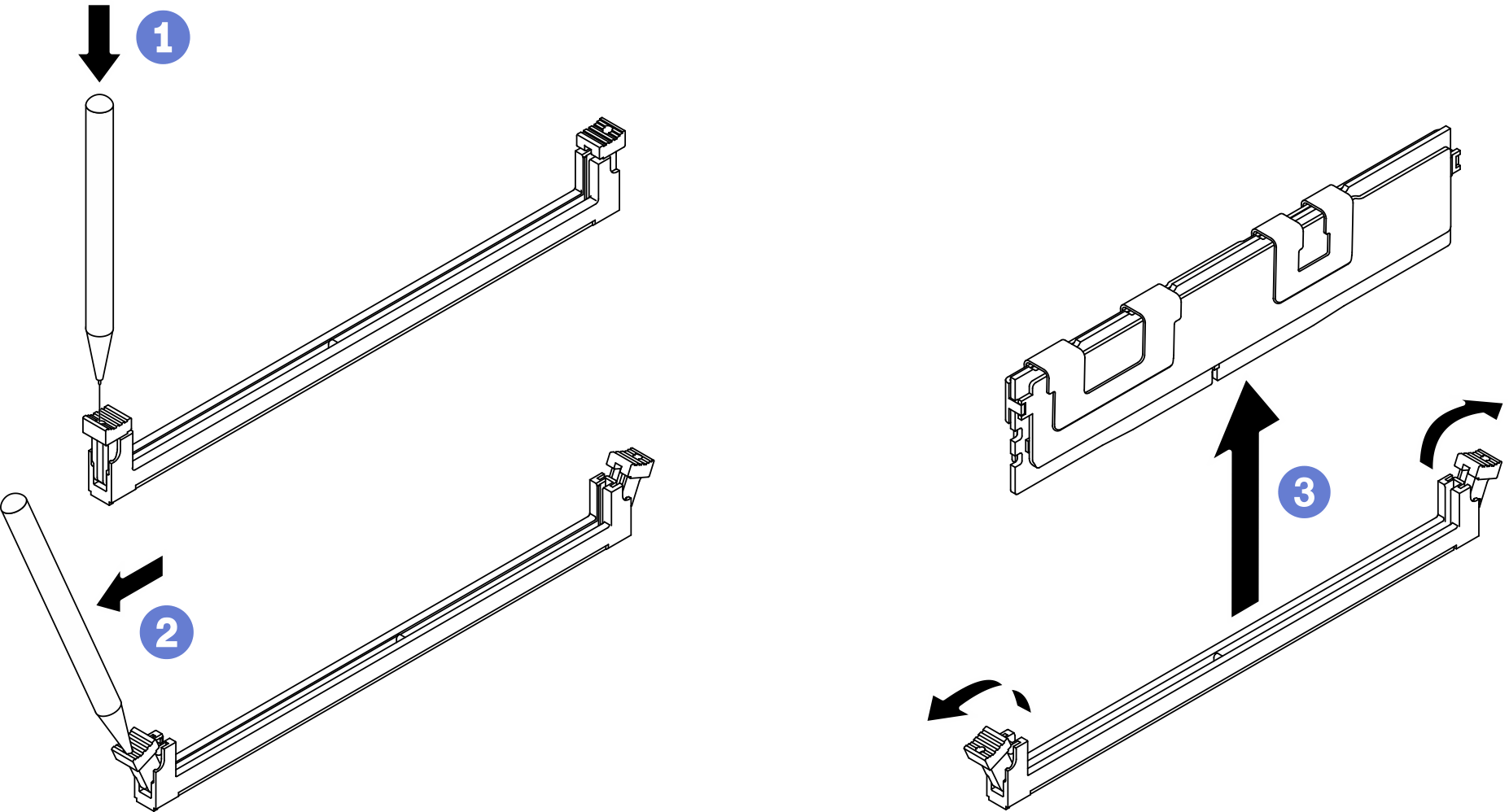
A memory module slot must be installed with a memory module or a memory module filler. See Install a memory module.
Change and save the new configuration information by using the Setup utility. When you turn on the compute node, a message indicates that the memory configuration has changed. Start the Setup utility and select Save Setting to save changes. (see the Lenovo ThinkSystem SN550 V2 Type 7Z69 Setup Guide for more information)
If you are instructed to return the component or optional device, follow all packaging instructions, and use any packaging materials for shipping that are supplied to you.
Demo video