Install an M.2 drive
Use this information to install an M.2 drive in the M.2 backplane.
Before you install an M.2 drive in the M.2 backplane, complete the following steps:
Read Installation Guidelines to ensure that you work safely.
- Touch the static-protective package that contains the M.2 drive to any unpainted metal surface on the chassis or any unpainted metal surface on any other grounded rack component; then, remove the M.2 drive from the package.
- Make sure the retainer on the M.2 backplane is in the correct keyhole to accommodate the particular size of the M.2 drive you wish to install (see Adjust the position of the retainer on the M.2 backplane).
To install an M.2 drive in the M.2 backplane, complete the following steps:
- Locate the connector on each side of the M.2 backplane.Note
Some M.2 backplanes support two identical M.2 drives. When two drives are installed, align and support both drives when sliding the retainer forward to secure the drives.
Install the M.2 drive in slot 0 first.
Figure 1. M.2 drive slot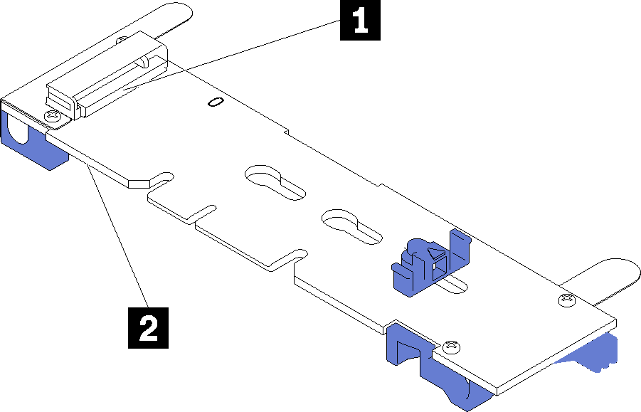
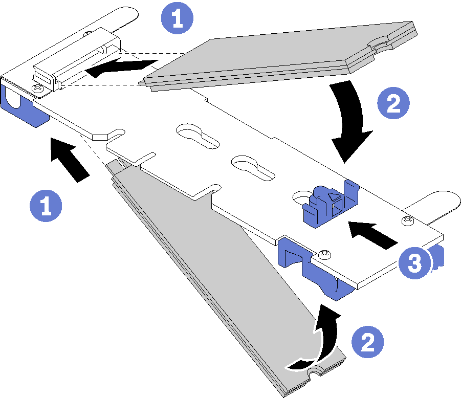
Table 1. M.2 drive slot 1 Slot 0 2 Slot 1 - Insert the M.2 drive at an angle (approximately 30 degrees) into the connector and rotate it until the notch catches on the lip of the retainer; then, slide the retainer forward (toward the connector) to secure the M.2 drive in the M.2 backplane.Figure 2. M.2 drive installation
 AttentionWhen sliding the retainer forward, make sure the two nubs on the retainer enter the small holes on the M.2 backplane. Once they enter the holes, you will hear a soft “click” sound.Figure 3. M.2 drive installation
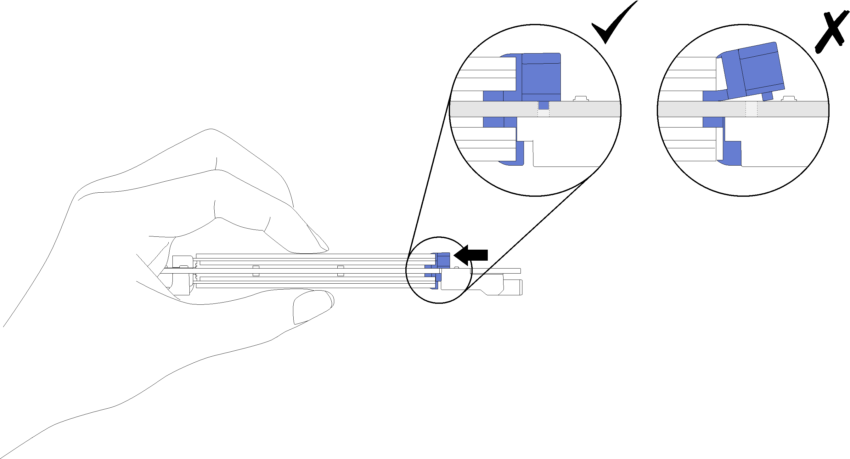
After you install an M.2 drive in the M.2 backplane, complete the following steps:
Install the M.2 backplane (see Install the M.2 backplane).
Install the compute node cover (see Install the compute node cover ).
Install the compute node into the chassis (see Install the compute node in the chassis ).
Power on the compute node.
Demo video
Give documentation feedback