Memory configuration
Memory performance depends on several variables, such as memory mode, memory speed, memory ranks, memory population and processor.
Information about optimizing memory performance and configuring memory is available at the Lenovo Press website:
In addition, you can take advantage of a memory configurator, which is available at the following site:
Lenovo Enterprise Solutions Configurator (Memory Configurations)
Specific information about the required installation order of memory modules in your compute node based on the system configuration and memory mode that you are implementing is shown below.
Figure 1. DIMM and processor location
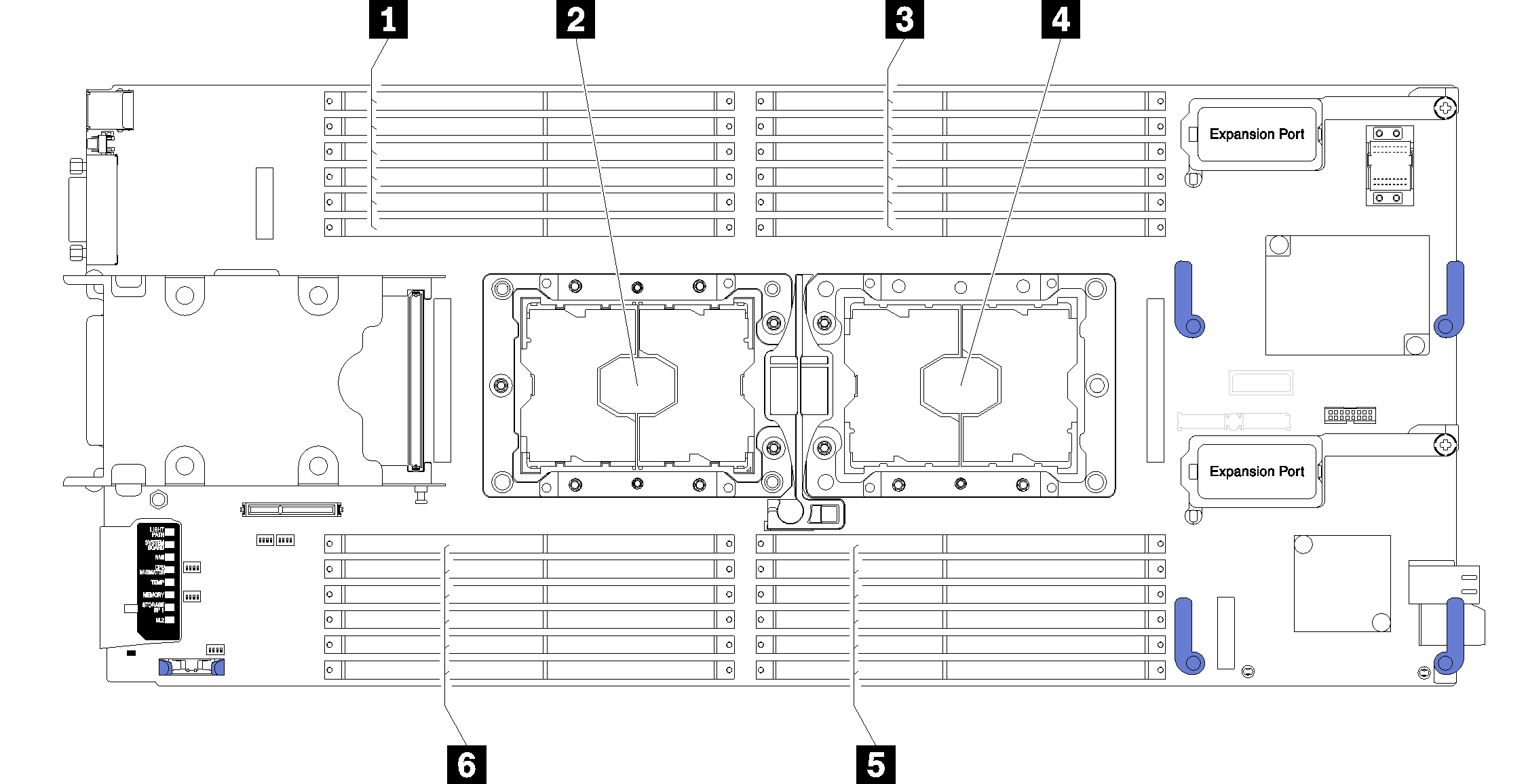
| 1 DIMM connectors 13–18 | 4 Processor socket 1 |
| 2 Processor socket 2 | 5 DIMM connectors 7–12 |
| 3 DIMM connectors 1–6 | 6 DIMM connectors 19–24 |
| Integrated Memory Controller (iMC) | Controller 0 | Controller 1 | |||||||||||
| Channel | Channel 2 | Channel 1 | Channel 0 | Channel 0 | Channel 1 | Channel 2 | |||||||
| Slot | 0 | 1 | 0 | 1 | 0 | 1 | 1 | 0 | 1 | 0 | 1 | 0 | |
| DIMM connector (processor 1) | 1 | 2 | 3 | 4 | 5 | 6 | 7 | 8 | 9 | 10 | 11 | 12 | |
| DIMM connector (processor 2) | 24 | 23 | 22 | 21 | 20 | 19 | 18 | 17 | 16 | 15 | 14 | 13 | |
Give documentation feedback