Front I/O assembly
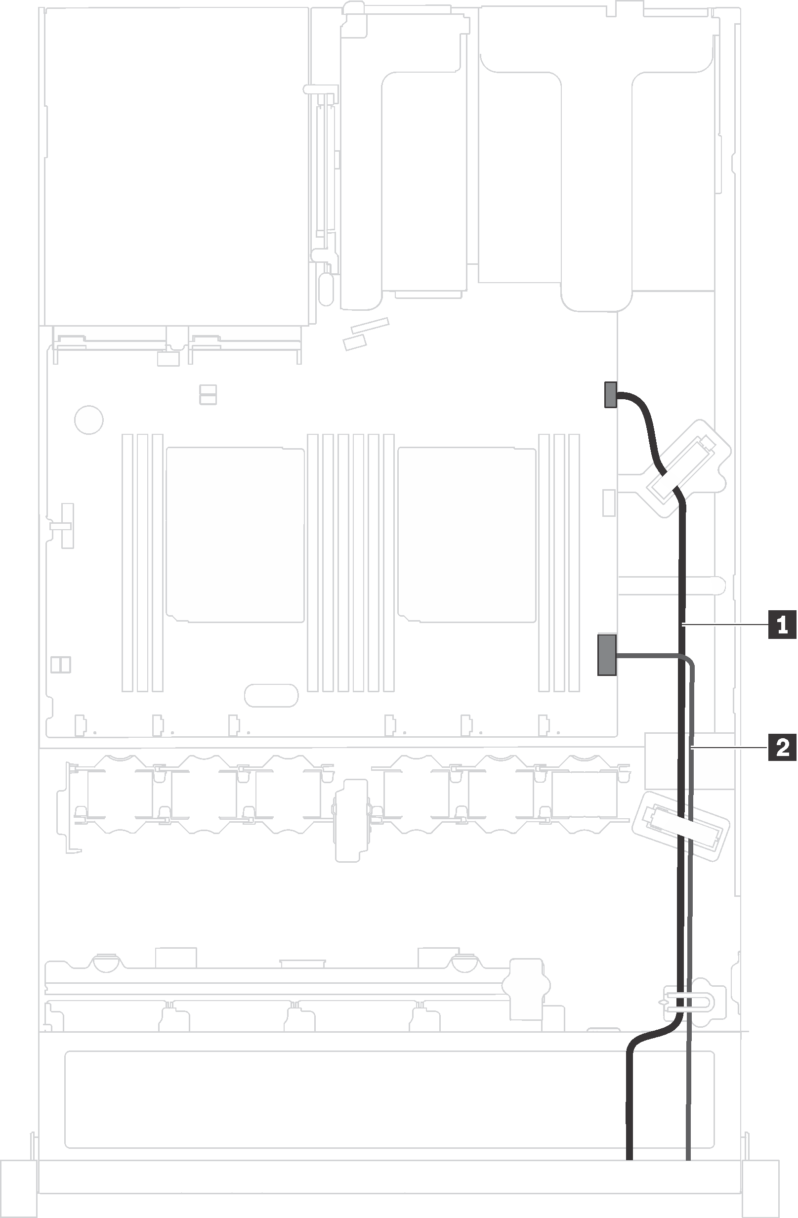
Use this section to understand the cable routing for the front I/O assembly.
Figure 1. Cable routing for the front I/O assembly


| From | To |
|---|---|
| 1 Front USB cable | Front USB connector on the system board |
| 2 Operator-information-panel cable | Operator-information-panel connector on the system board |
Give documentation feedback