2,5 pollici (10 NVMe)
| Configuration | Rear BP | Storage controller | ||
| Qty. | Type | Qty. | Type | |
| Config. 1 | ||||
| Config. 2 | 2 | NVMe Retimer card | ||
| Config. 3 | 1 | 2 x 2.5" NVMe | ||
| Config. 4 | 1 | 2 x 2.5" SAS/SATA | ||
A seconda delle configurazioni del server, fare riferimento a una delle sezioni che seguono per informazioni sull'instradamento dei cavi.
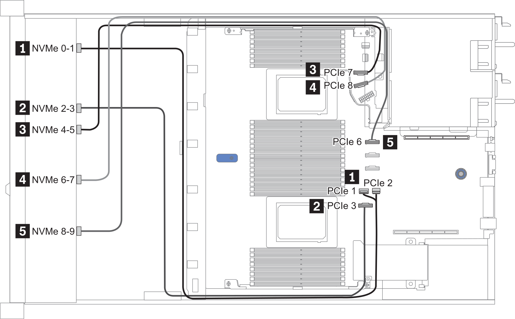
Configurazione 1:
Front BP: 10 x 2.5'' Anybay BP used as pure NVMe BP
| Config. | BP anteriore | Scheda di sistema |
| 1 | NVMe 0-1 | PCIe 1, PCIe 2 |
| NVMe 2-3 | PCIe 3 | |
| NVMe 4-5 | PCIe 7 | |
| NVMe 6-7 | PCIe 8 | |
| NVMe 8-9 | PCIe 6 |
Esempio
Figura 1. Configuration 1
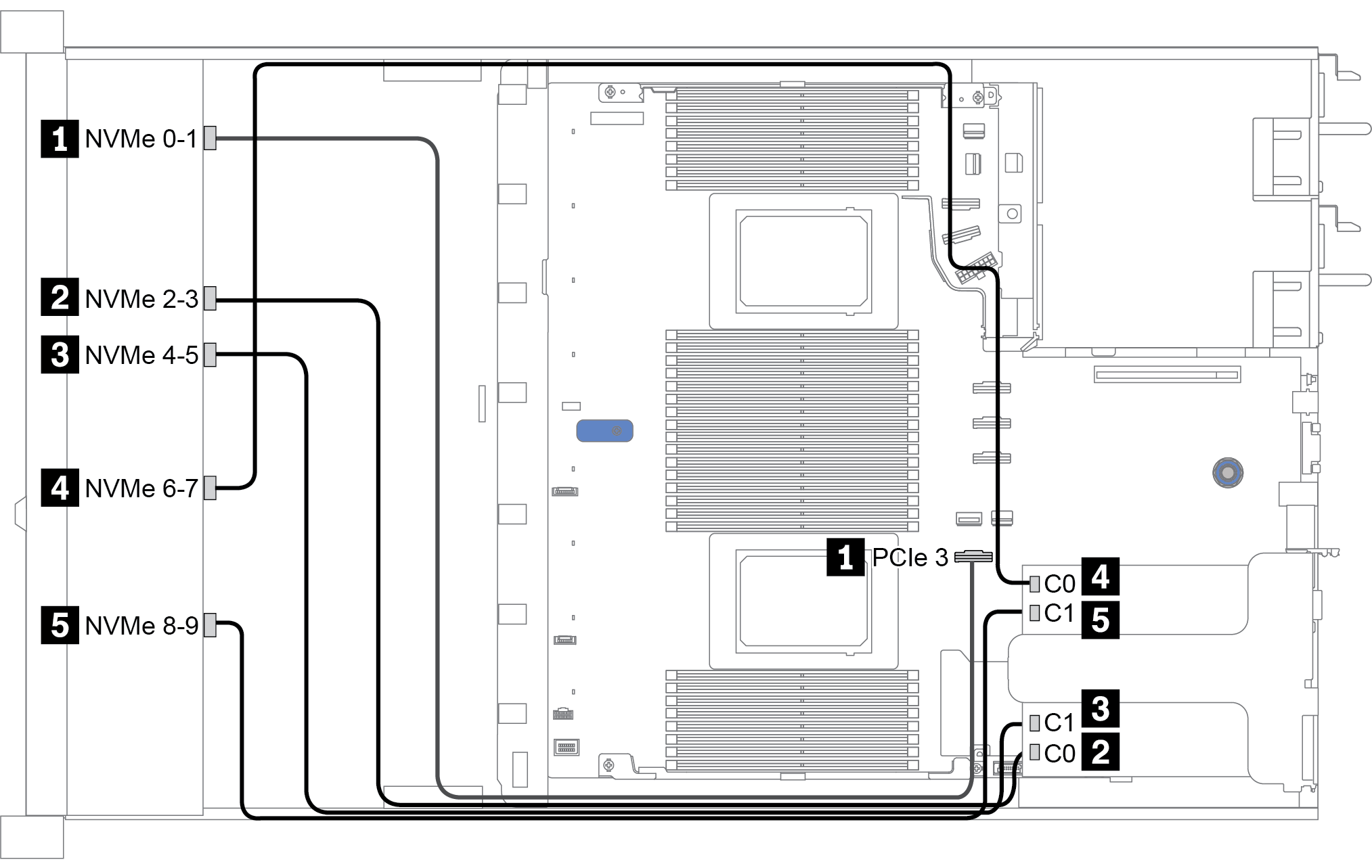
Configurazione 2:
| Config. | BP anteriore | Scheda di sistema | Scheda retimer | |
| Slot 1 | Slot 2 | |||
| 2 | NVMe 0-1 | PCIe 3 | ||
| NVMe 2-3 | C0 | |||
| NVMe 4-5 | C1 | |||
| NVMe 6-7 | C0 | |||
| NVMe 8-9 | C1 | |||
Esempio
Figura 2. Configuration 2
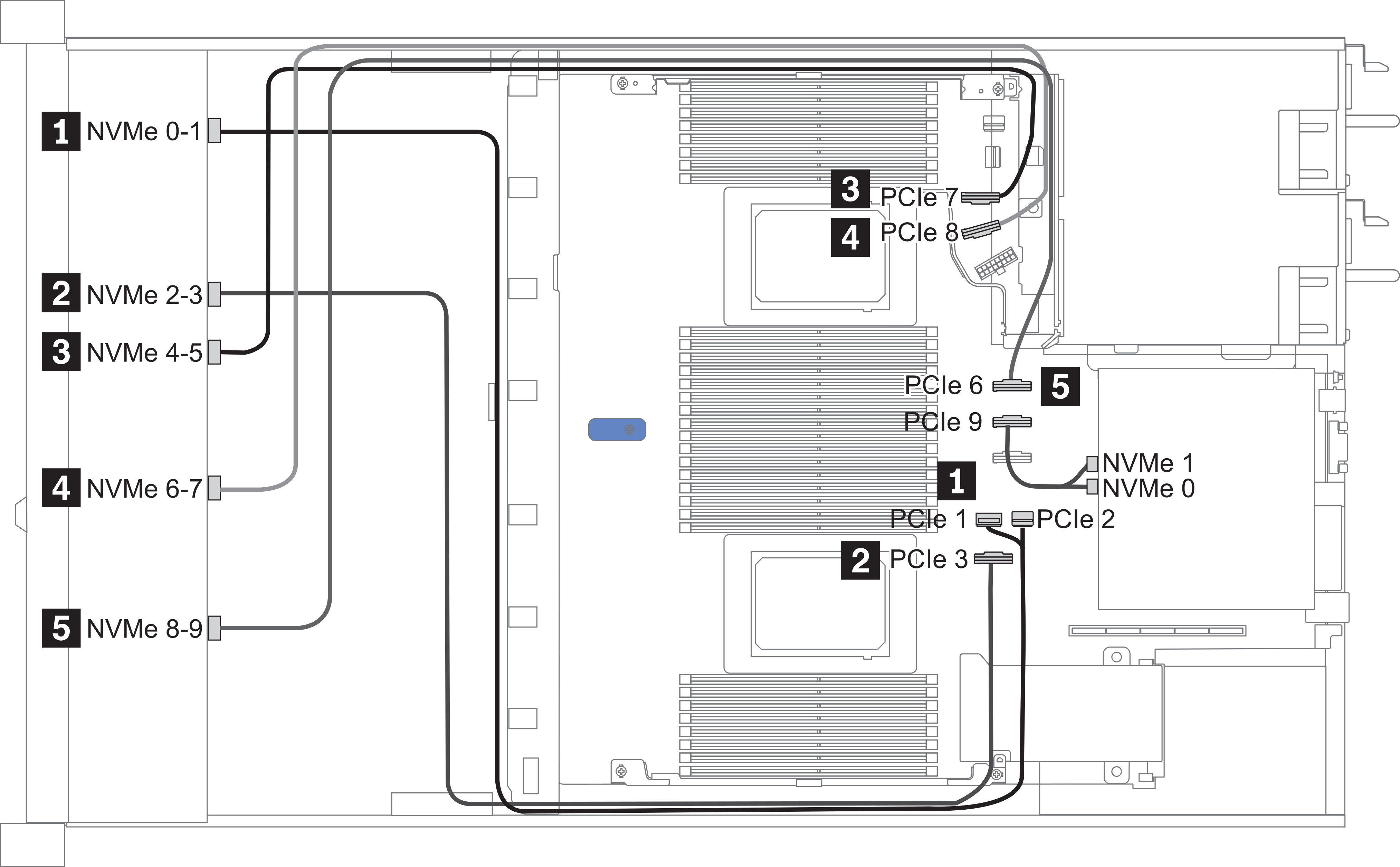
Configuration 3 – 4:
Front BP: 10 x 2.5'' Anybay BP used as pure NVMe BP
Rear BP: 2 x 2.5'' NVMe BP/ 2 x 2.5'' SAS/SATA BP
| Config. | Front BP | Rear BP | System board |
| 3 | NVMe 0-1 | PCIe 1, PCIe 2 | |
| NVMe 2-3 | PCIe 3 | ||
| NVMe 4-5 | PCIe 7 | ||
| NVMe 6-7 | PCIe 8 | ||
| NVMe 8-9 | PCIe 6 | ||
| NVMe 0, NVMe 1 | PCIe 9 | ||
| 4 | NVMe 0-1 | PCIe 1, PCIe 2 | |
| NVMe 2-3 | PCIe 3 | ||
| NVMe 4-5 | PCIe 7 | ||
| NVMe 6-7 | PCIe 8 | ||
| NVMe 8-9 | PCIe 6 | ||
| SAS | PCIe 5 |
Esempio
Figura 3. Configuration 3
Envoyer des commentaires