LCD diagnostics panel/handset
The LCD diagnostics panel is a component attached to the front of the server, the external LCD diagnostics handset is an external device that can be connected to the server with a cable. Functions of the integrated component and the external device are the same, both of them can be used to quickly access system information such as active errors, system status, firmware, network information, and health information.
Where to find the LCD diagnostics panel
| Location | Callout |
|---|---|
The LCD diagnostics panel is attached to the front of the server. 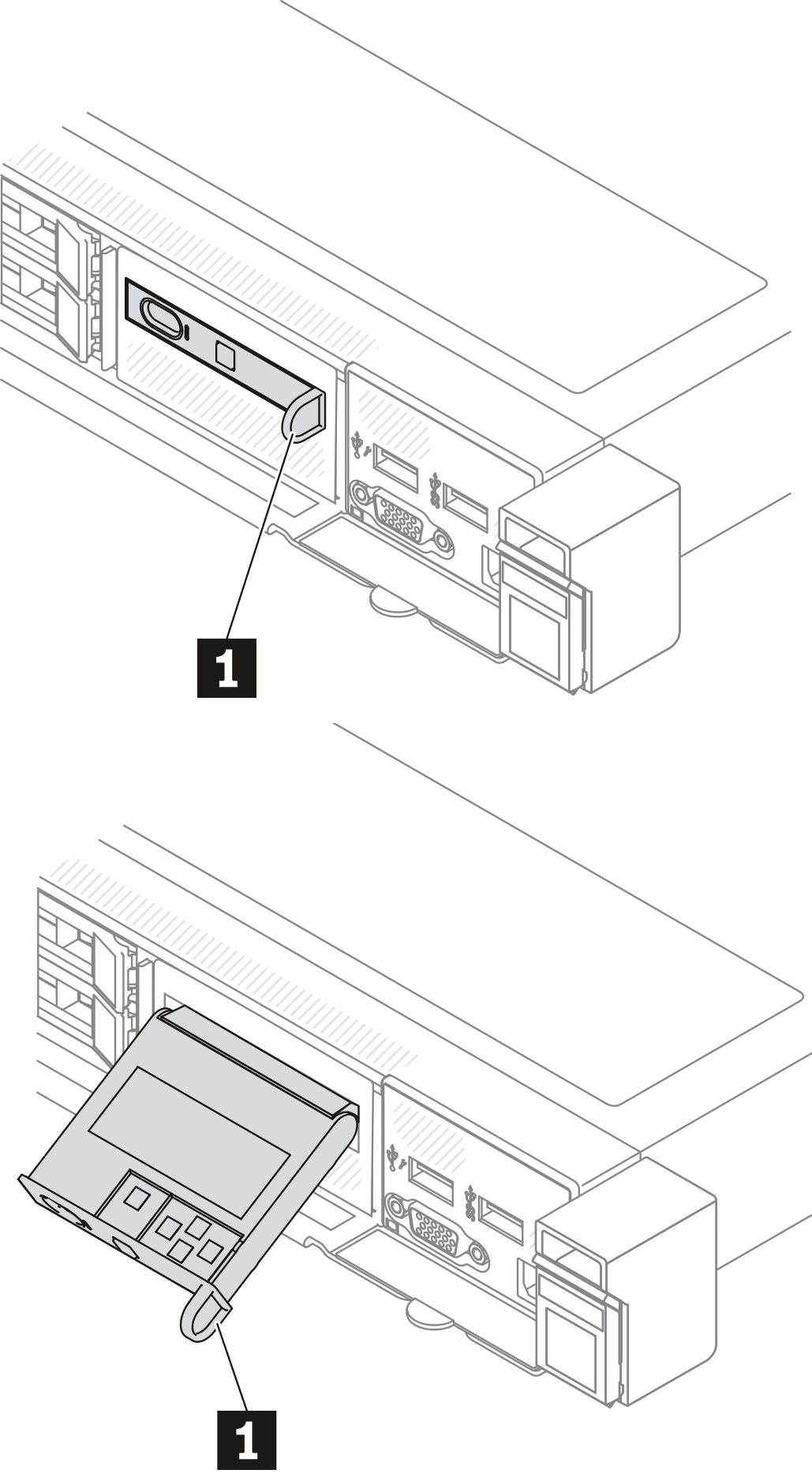 | 1 The handle with which the panel can be pulled out and inserted into the rack. Note
|
Where to find the external LCD diagnostics handset
| Location | Callout |
|---|---|
The external LCD diagnostics handset is connected to the server with an external cable. 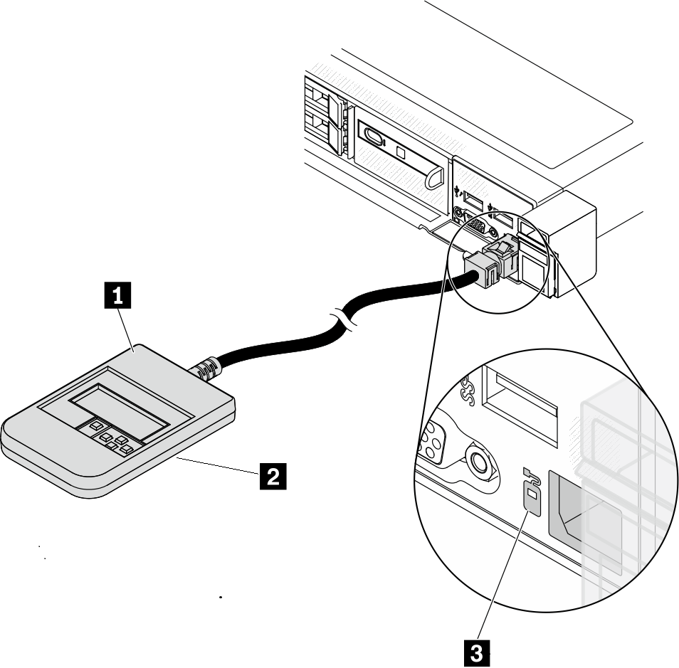 | 1 The LCD diagnostics handset that can be connected to the server with an external cable. 2 The magnetic bottom with which the device can be attached to the top or side of the rack. This is helpful and can free up both hands for certain service tasks. 3 The external diagnostics connector on the front of the server that can be used to connect an external LCD diagnostics handset. |
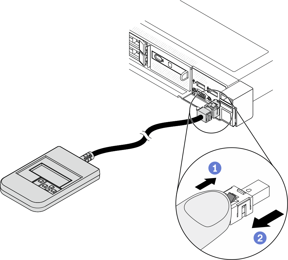
Step 1. Press the plastic clip on the plug in the shown direction. Step 2. Gently pull out the cable from the connector while keeping the clip pressed down.
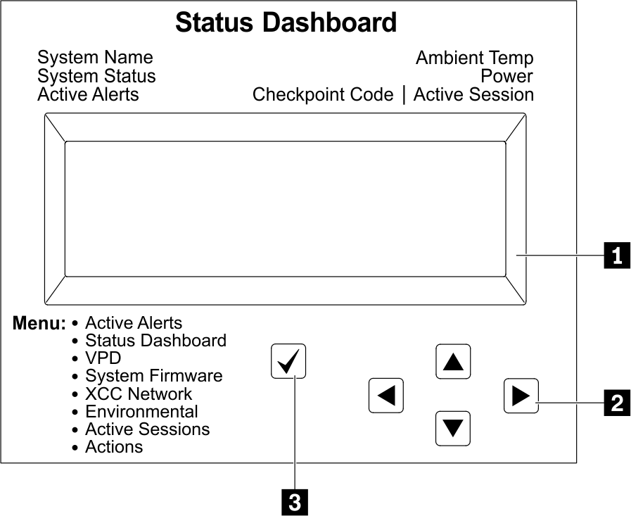
Display panel overview
Both the integrated panel and the external handset consist of an LCD display and 5 navigation buttons.
Options flow diagram
The LCD diagnostics panel/handset shows various system information. Navigate through the options with the scroll keys.
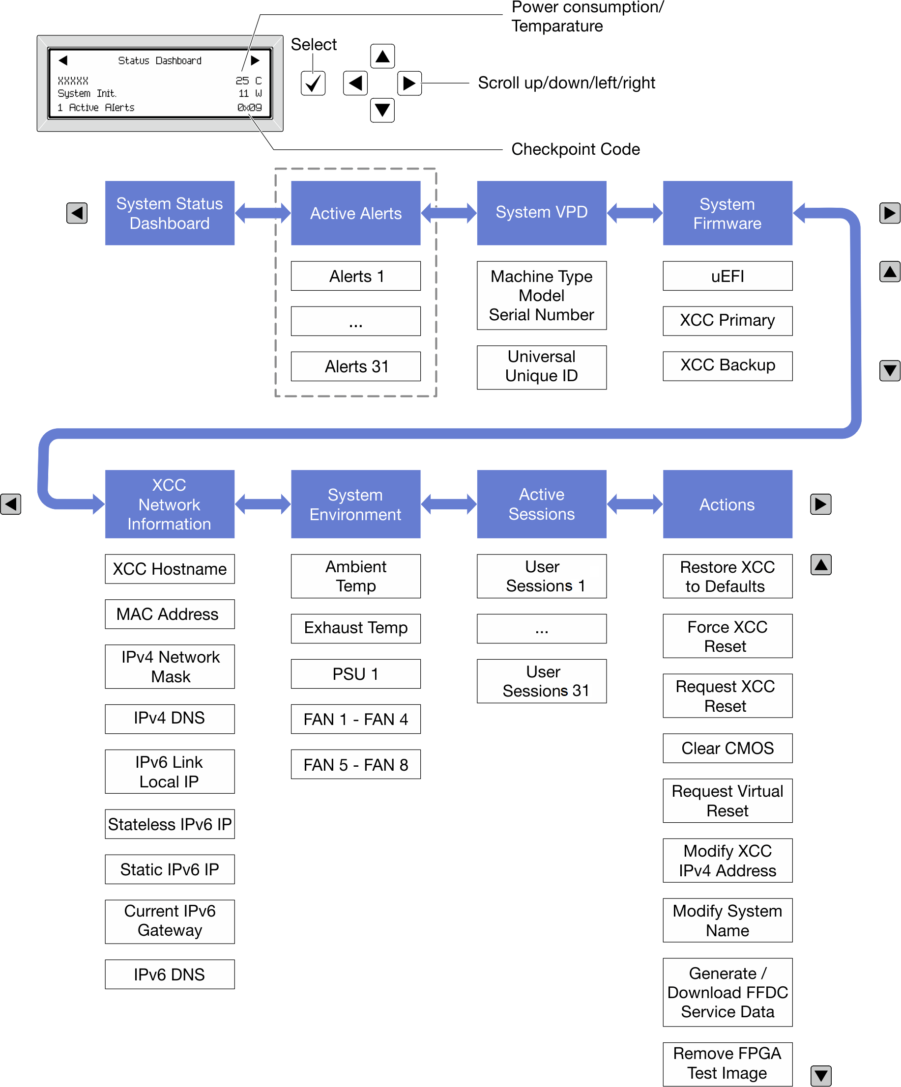
Full menu list
Following is the list of options available on the LCD diagnostics panel/handset. Switch between an option and the subordinate information entries with the select button, and switch among options or information entries with the scroll buttons.
| Home Menu | Example |
|---|---|
1 System name 2 System status 3 Active alert quantity 4 Temperature 5 Power consumption 6 Checkpoint code | 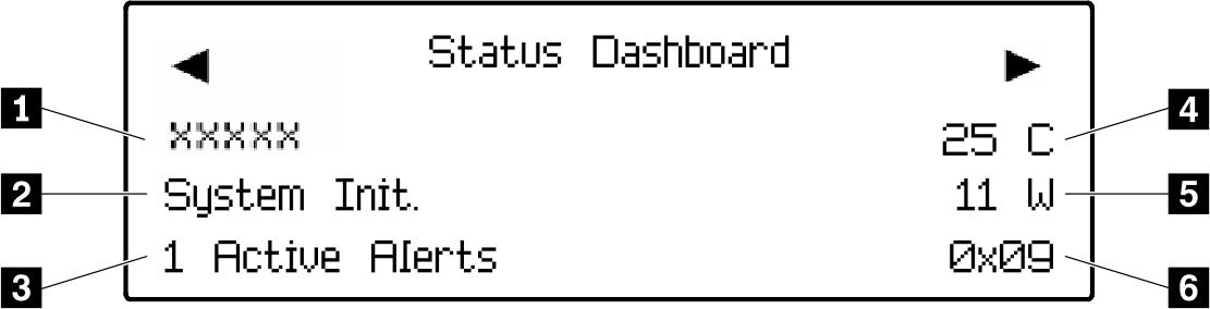 |
| Sub Menu | Example |
|---|---|
Home screen: Active error quantity Note The Active Alertsmenu displays only the quantity of active errors. If no errors occur, the Active Alertsmenu will not be available during navigation. | 1 Active Alerts |
Details screen:
| |
| Sub Menu | Example |
|---|---|
| |
| Sub Menu | Example |
|---|---|
UEFI
| |
XCC Primary
| |
XCC Backup
| |
| Sub Menu | Example |
|---|---|
Note Only the MAC address that is currently in use is displayed (extension or shared). | |
| Sub Menu | Example |
|---|---|
| |
| Sub Menu | Example |
|---|---|
| Quantity of active sessions | |
| Sub Menu | Example |
|---|---|
Several quick actions supported for users
| |