Backplane anteriori + centrale + posteriore: NVMe a 24 vani + NVMe a 8 vani (due AnyBay a 4 vani) + NVMe a 4 vani
Questa sezione fornisce informazioni sull'instradamento dei cavi per la configurazione NVMe a 24 vani da 2,5 pollici + NVMe a 8 vani da 2,5 pollici (con due backplane AnyBay a 4 vani da 2,5 pollici) + NVMe a 4 vani da 2,5 pollici con quattro schede retimer.
Collegamenti tra i connettori: 1 ↔ 1, 2 ↔ 2, 3 ↔ 3, ... n ↔ n
Instradamento dei cavi del backplane anteriore
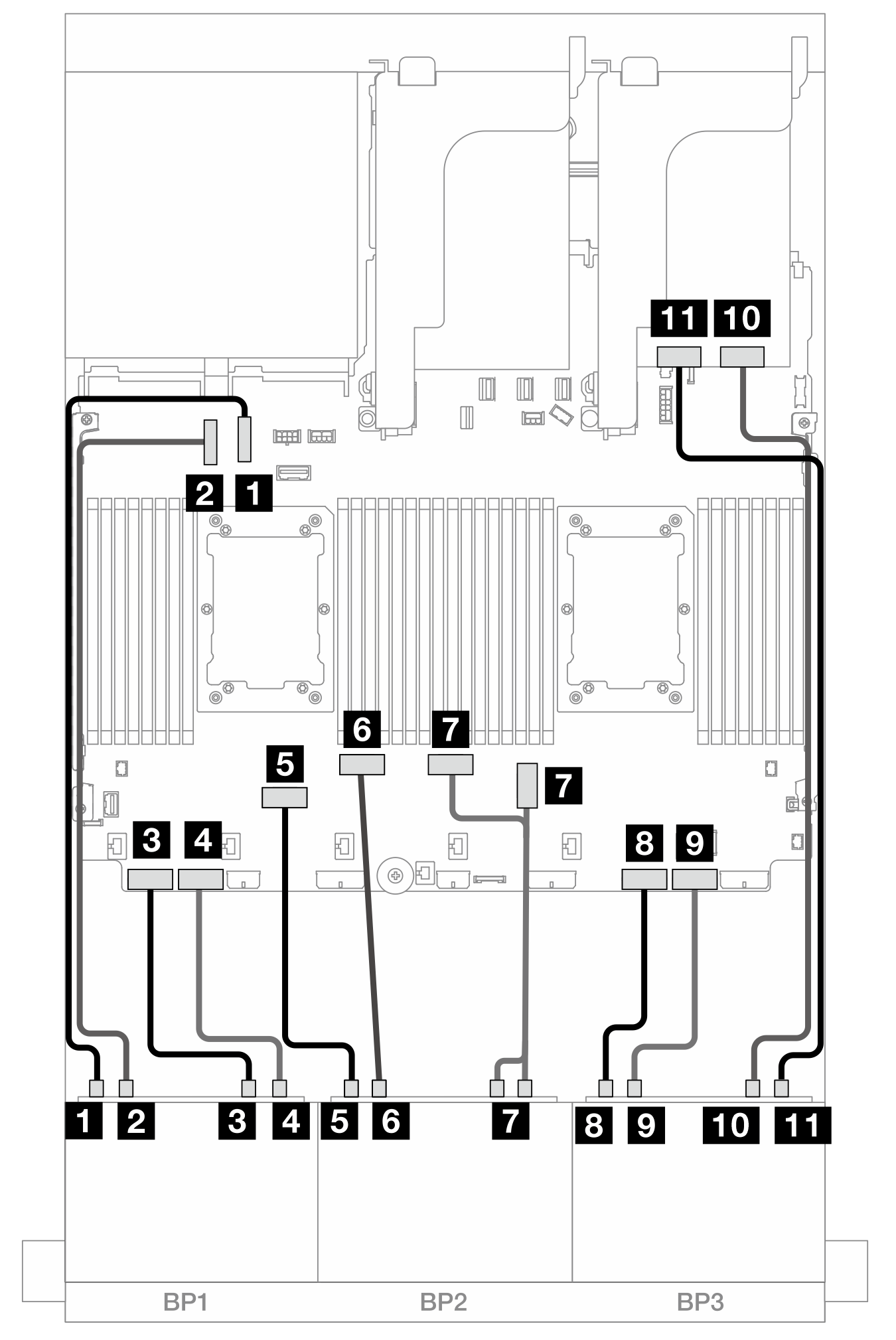
Figura 1. Instradamento dei cavi NVMe ai connettori integrati e a una scheda retimer
| Da | A |
|---|---|
| 1 Backplane 1: NVMe 0-1 | Integrato: PCIe 10 |
| 2 Backplane 1: NVMe 2-3 | Integrato: PCIe 9 |
| 3 Backplane 1: NVMe 4-5 | Integrato: PCIe 8 |
| 4 Backplane 1: NVMe 6-7 | Integrato: PCIe 7 |
| 5 Backplane 2: NVMe 0-1 | Integrato: PCIe 6 |
| 6 Backplane 2: NVMe 2-3 | Integrato: PCIe 5 |
| 7 Backplane 2: NVMe 4-5, 6-7 | Integrato: PCIe 3, 4 |
| 8 Backplane 3: NVMe 0-1 | Integrato: PCIe 2 |
| 9 Backplane 3: NVMe 2-3 | Integrato: PCIe 1 |
| 10 Backplane 3: NVMe 4-5 | Retimer: C0 |
| 11 Backplane 3: NVMe 6-7 | Retimer: C1 |
Instradamento dei cavi del backplane centrale
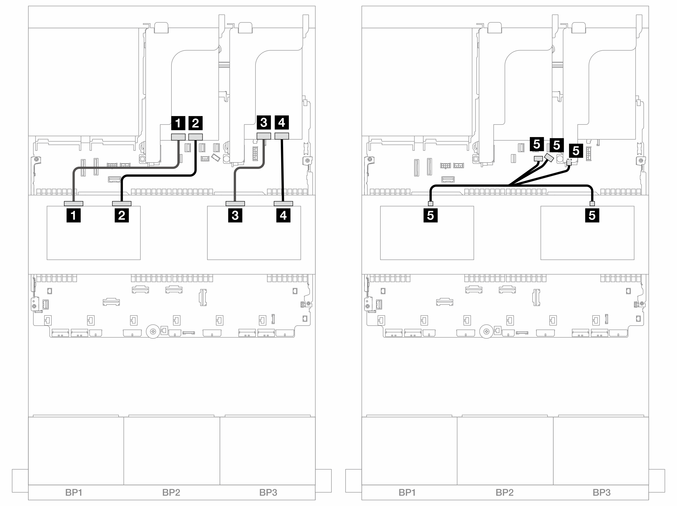
Figura 2. Instradamento dei cavi del backplane centrale
| Da | A |
|---|---|
| 1 Backplane 5: NVMe 0-1 | Retimer: C1 |
| 2 Backplane 5: NVMe 2-3 | Retimer: C0 |
| 3 Backplane 6: NVMe 0-1 | Retimer: C1 |
| 4 Backplane 6: NVMe 2-3 | Retimer: C0 |
5
|
|
Instradamento dei cavi del backplane posteriore
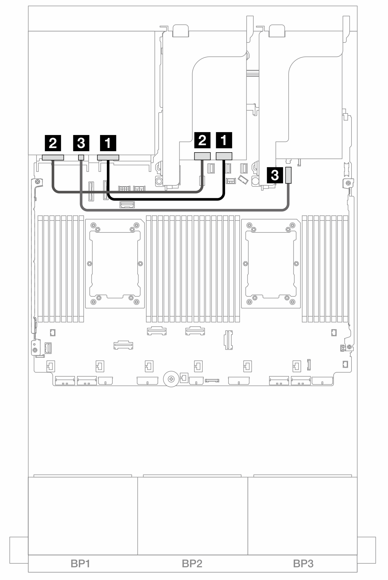
Figura 3. Instradamento dei cavi del backplane posteriore
| Da | A |
|---|---|
| 1 Backplane 4: NVMe 0-1 | Retimer: C0 |
| 2 Backplane 4: NVMe 2-3 | Retimer: C1 |
| 3 Backplane 4: PWR | Integrato: connettore di alimentazione da 7 mm |
Envoyer des commentaires