ThinkSystem SR655 (7Y00, 7Z01)
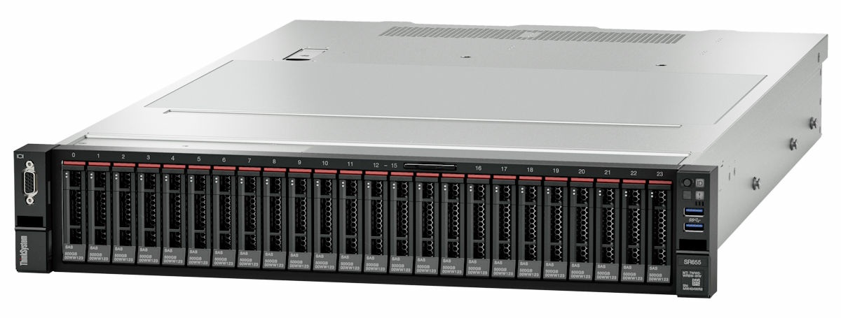
ThinkSystem™ SR655 (tipo di macchina: 7Y00 7Z01) è un server 2U a 1 socket, basato sulla nuova famiglia di processori AMD EPYC 7002. Il server offre un'ampia selezione di unità e configurazioni degli slot, con prestazioni elevate ed espansione per vari carichi di lavoro IT. Grazie alla combinazione di prestazioni e flessibilità, il server è una scelta ideale per le aziende di qualsiasi dimensione.
- Risorse e download
In questa sezione vengono forniti documenti pratici, download di driver e firmware e risorse di supporto. - Contenuto della confezione del server
Quando si riceve il server, verificare che la spedizione contenga tutto il materiale previsto. - Caratteristiche
Le prestazioni, la facilità d'uso, l'affidabilità e le funzionalità di espansione rappresentavano considerazioni fondamentali nella progettazione del server. Queste caratteristiche di progettazione rendono possibile la personalizzazione dell'hardware del sistema al fine di soddisfare le proprie necessità attuali e fornire capacità di espansione flessibili per il futuro. - Specifiche
Le seguenti informazioni forniscono un riepilogo delle funzioni e delle specifiche del server. In base al modello, alcune funzioni potrebbero non essere disponibili o alcune specifiche potrebbero non essere valide. - Opzioni di gestione
La gamma di funzionalità XClarity e altre offerte di gestione del sistema descritte in questa sezione sono disponibili per facilitare la gestione dei server in modo più pratico ed efficiente. - Componenti del server
Questa sezione fornisce informazioni che consentono di individuare i componenti del server. - Configurazione dell'hardware del server
Per installare il server, installare tutte le opzioni acquistate, cablare il server, configurare e aggiornare il firmware, quindi installare il sistema operativo. - Configurazione di sistema
Completare queste procedure per configurare il sistema. - Procedure di sostituzione hardware
Questa sezione illustra le procedure di installazione e rimozione di tutti i componenti di sistema che richiedono manutenzione. Ciascuna procedura di sostituzione di un componente indica tutte le attività che devono essere eseguite per accedere al componente da sostituire. - Determinazione dei problemi
Utilizzare le informazioni in questa sezione per isolare e risolvere i problemi riscontrati durante l'utilizzo del server. - Messaggi
Quando si tenta di risolvere problemi relativi al server, la best practice consiste nel partire dal log eventi dell'applicazione che gestisce il server: - Suggerimenti tecnici
Lenovo aggiorna costantemente il sito Web di supporto con i suggerimenti e le tecniche più recenti da utilizzare per risolvere i problemi che si potrebbero riscontrare con il server. Questi suggerimenti tecnici (noti anche come comunicati di servizio) descrivono le procedure per la risoluzione di problemi correlati all'utilizzo del server. - Avvisi di sicurezza
Lenovo è impegnata a sviluppare prodotti e servizi in base ai più elevati standard di sicurezza, al fine di proteggere i propri clienti e i loro dati. Quando vengono segnalate potenziali vulnerabilità, è responsabilità del team Lenovo Product Security Incident Response Team (PSIRT) indagare e fornire ai clienti informazioni utili per mettere in atto misure di mitigazione del danno in attesa che sia disponibile una soluzione definitiva al problema. - Smontaggio dell'hardware per il riciclaggio
Seguire le istruzioni riportate in questa sezione per riciclare i componenti in conformità alle normative o alle disposizioni locali. - Richiesta di supporto e assistenza tecnica
Se è necessaria assistenza tecnica o se si desidera ottenere maggiori informazioni sui prodotti Lenovo, è disponibile una vasta gamma di risorse Lenovo.
Envoyer des commentaires