Front I/O connectors
This section provides cable routing information for the front I/O connectors, including the VGA connector, external diagnostics connector, front operator panel connectors, and front USB connector.
Front I/O connectors on rack latches
Note
When routing a cable on the rack latch, ensure that it is fixed on the upper frame of the cable retainer. For details, refer to Install the rack latches.
Figure 1. Front VGA connector and external diagnostics connector (left rack latch) 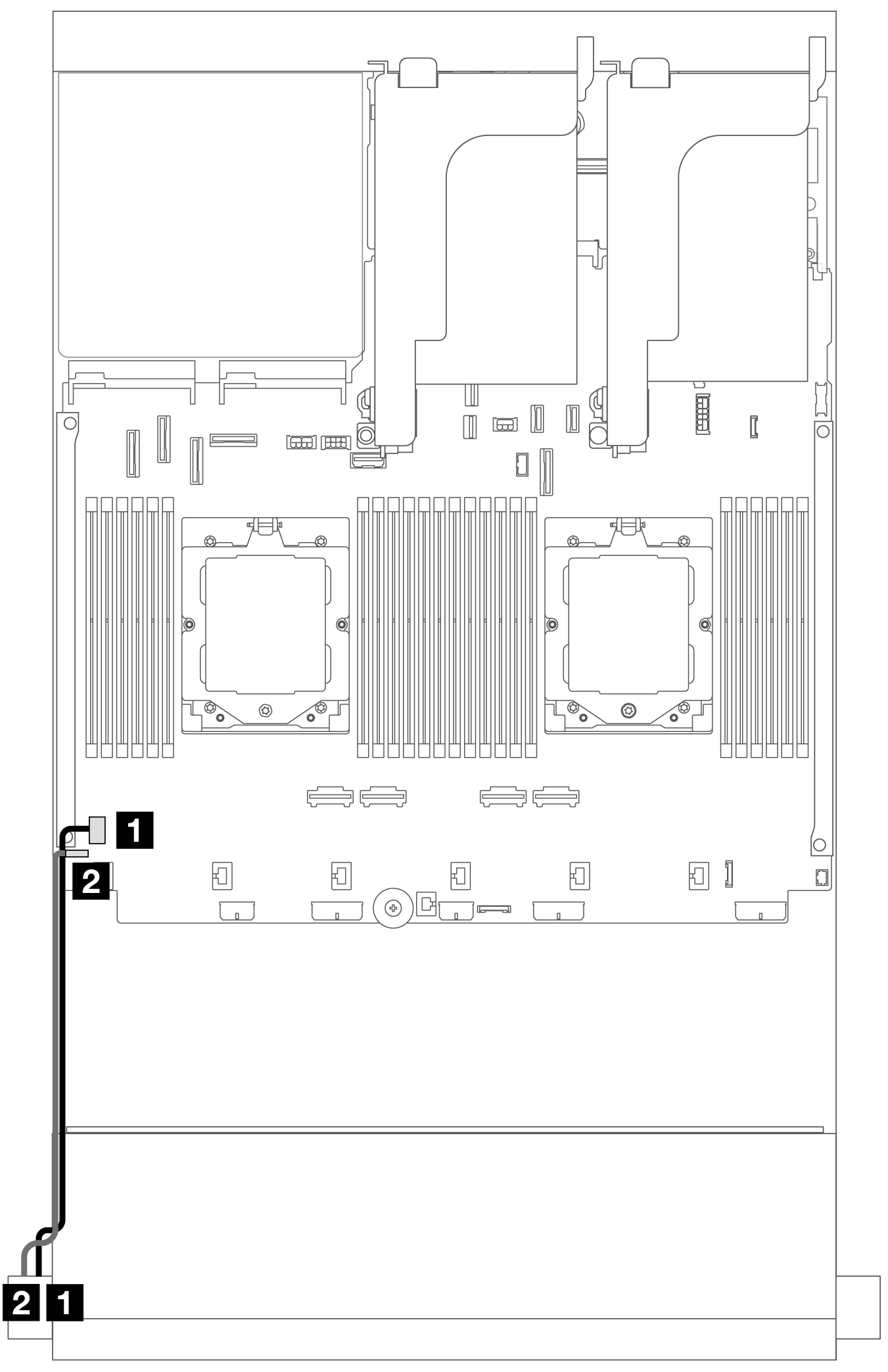 | Figure 2. Front operator panel and USB connectors (right rack latch) 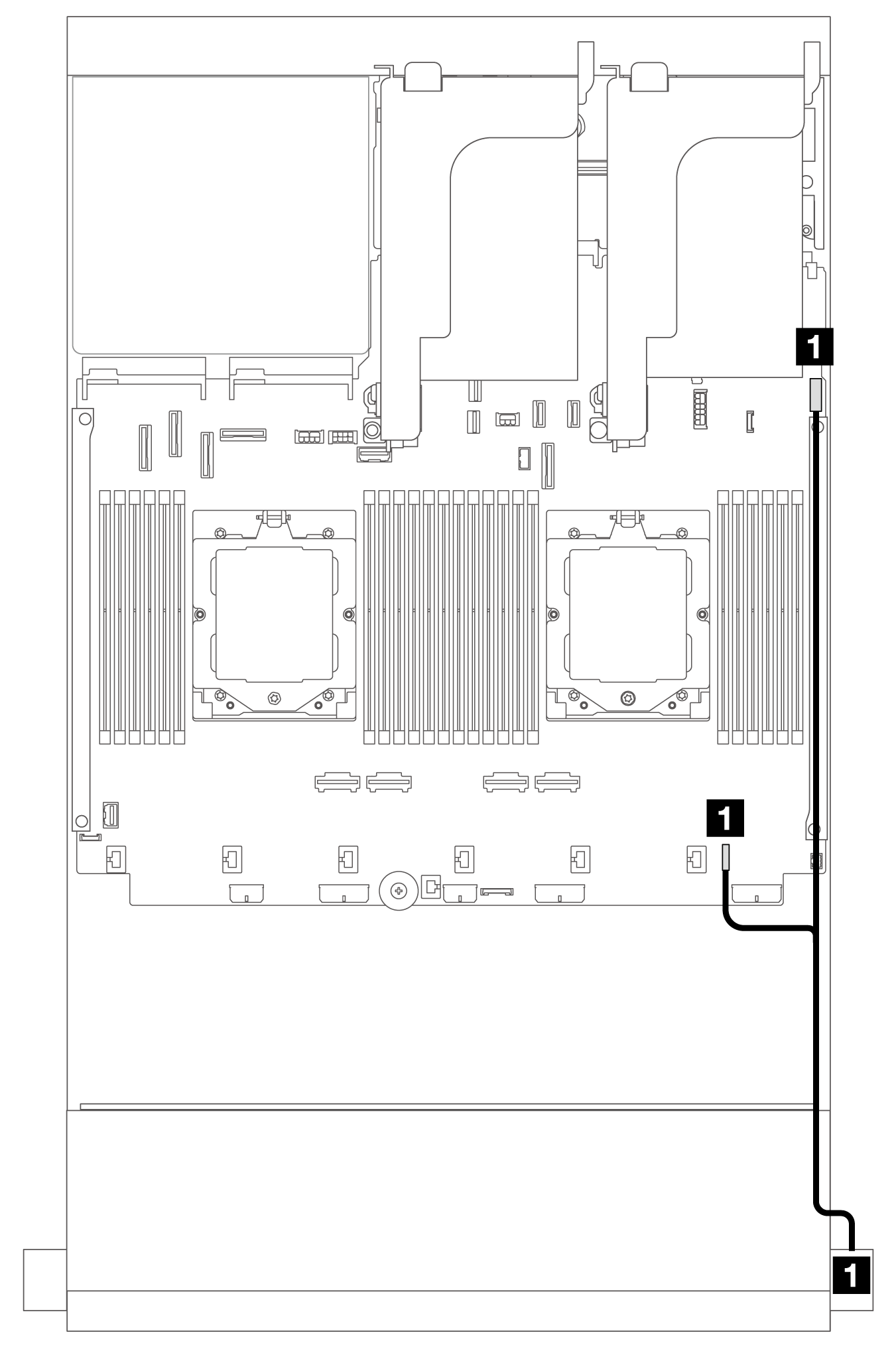 | ||
| From | To | From | To |
| 1 VGA cable | 1 VGA connector on the system board assembly | 1 Front operator panel and USB cable | 1 FIO and USB connectors on the system board assembly |
| 2 External diagnostics cable | 2 External diagnostics connector on the system board assembly | ||
Front I/O connectors on the media bay
The illustration shows the cable routing for the front operator panel and front USB connectors on the media bay.
Depending on the server model, the server might come with a front operator panel with an LCD display (called integrated diagnostics panel) or a front operator panel without an LCD display.
Figure 3. Front operator panel with an LCD display 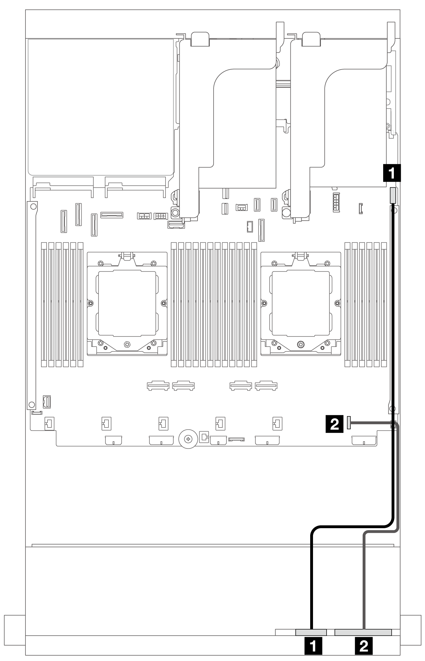 | Figure 4. Front operator panel without an LCD display 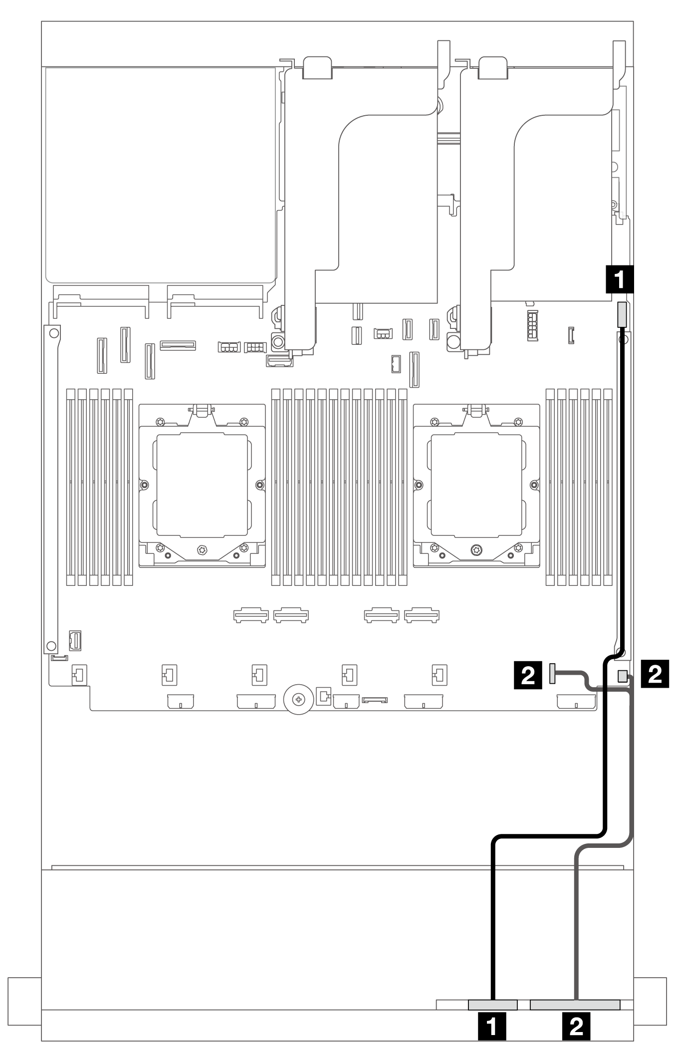 | ||
| From | To | From | To |
| 1 Front USB cable | 1 Front USB connector on the system board assembly | 1 Front USB cable | 1 Front USB connector on the system board assembly |
| 2 Front panel cable | 2 Front I/O connector on the system board assembly | 2 Front panel cable | 2 Front I/O connectors on the system board assembly |
Give documentation feedback