Rear view
The rear of the server provides access to several connectors and components.
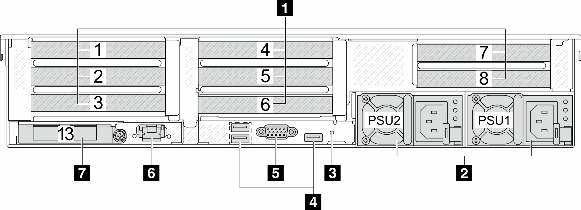
Rear view with four 2.5-inch rear drive bays and six PCIe slots
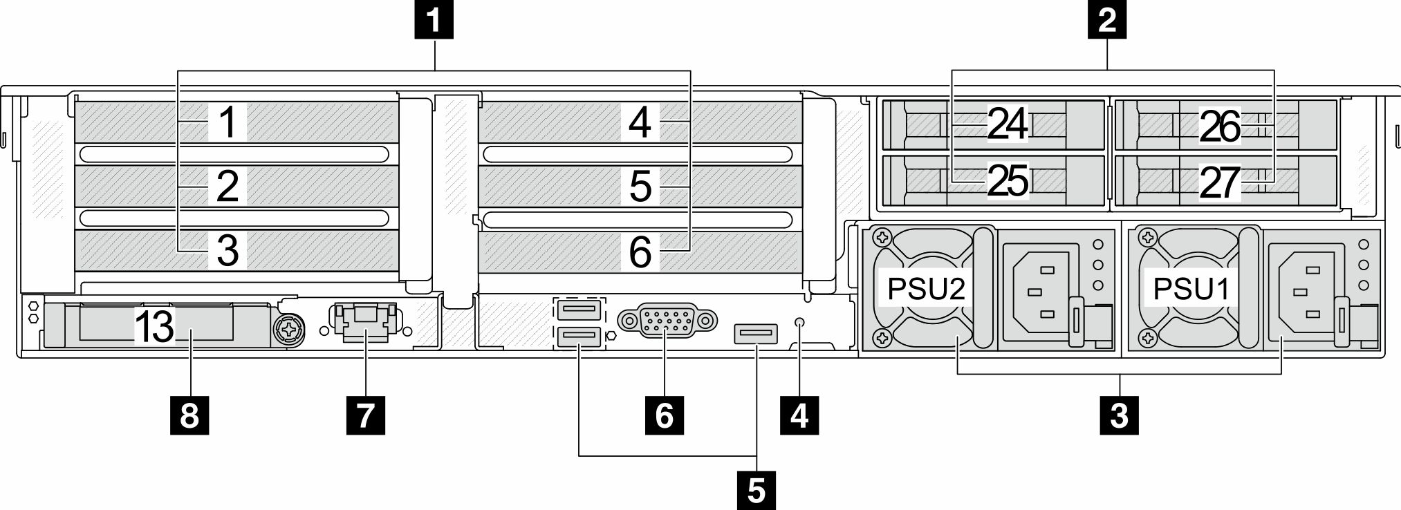
Rear view with eight 2.5-inch rear drive bays and four PCIe slots
Rear view with two 3.5-inch rear drive bays and four PCIe slots
Rear view with four 3.5-inch rear drive bays and two PCIe slots
Rear view with four 2.5-inch rear drive bays, five PCIe slots, and a DWCM
Rear view with eight 2.5-inch rear drive bays, three PCIe slots, and a DWCM
Rear view with two 3.5-inch rear drive bays, three PCIe slots, and a DWCM
Rear view with four 3.5-inch rear drive bays, one PCIe slot, and a DWCM
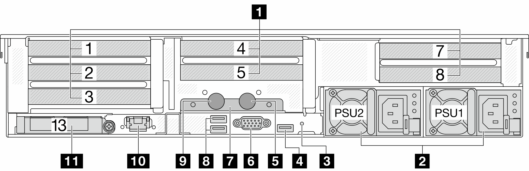
Rear view with eight PCIe slots
| Callout | Callout |
|---|---|
| 1 PCIe slots | 2 Power supply units |
| 3 NMI button | 4 USB 3 (5 Gbps) connectors (3) |
| 5 VGA connector | 6 XCC system management port |
| 7 Ethernet connectors on OCP module (optional) |
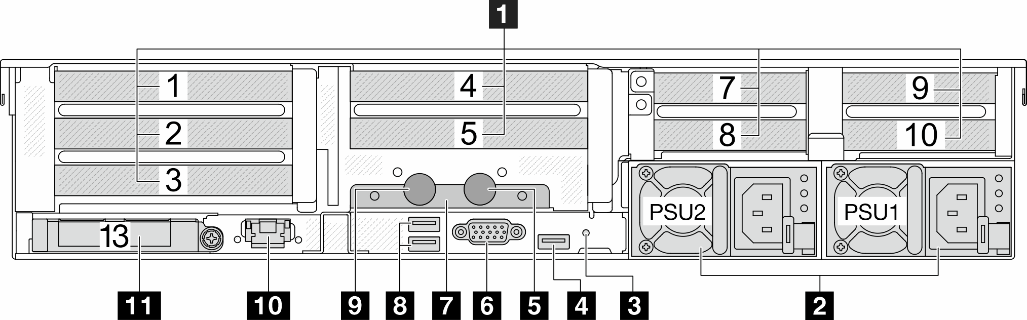
Rear view with ten PCIe slots
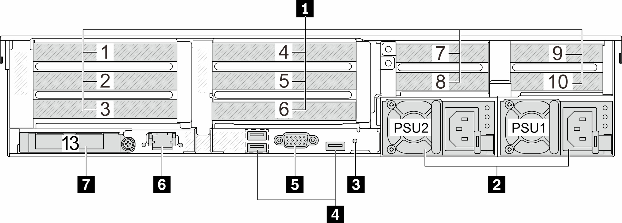
| Callout | Callout |
|---|---|
| 1 PCIe slots | 2 Power supply units |
| 3 NMI button | 4 USB 3 (5 Gbps) connectors (3) |
| 5 VGA connector | 6 XCC system management port |
| 7 Ethernet connectors on OCP module (optional) |
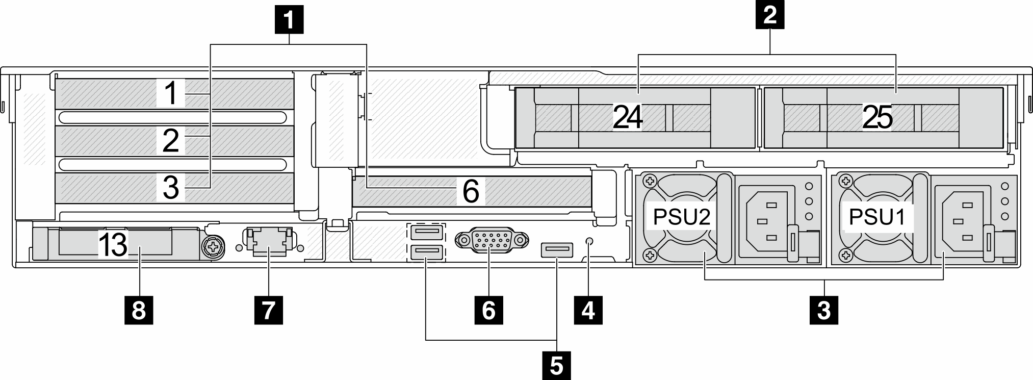
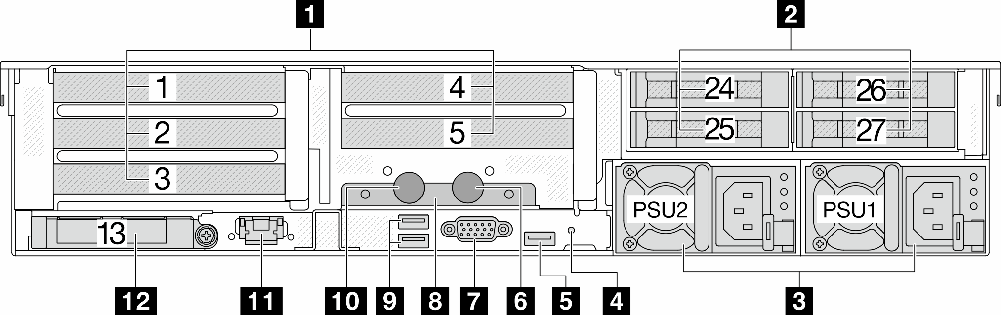
Rear view with four 2.5-inch rear drive bays and six PCIe slots
| Callout | Callout |
|---|---|
| 1 PCIe slots | 2 Rear 2.5-inch drive bays (4) |
| 3 Power supply units | 4 NMI button |
| 5 USB 3 (5 Gbps) connectors (3) | 6 VGA connector |
| 7 XCC system management port | 8 Ethernet connectors on OCP module (optional) |
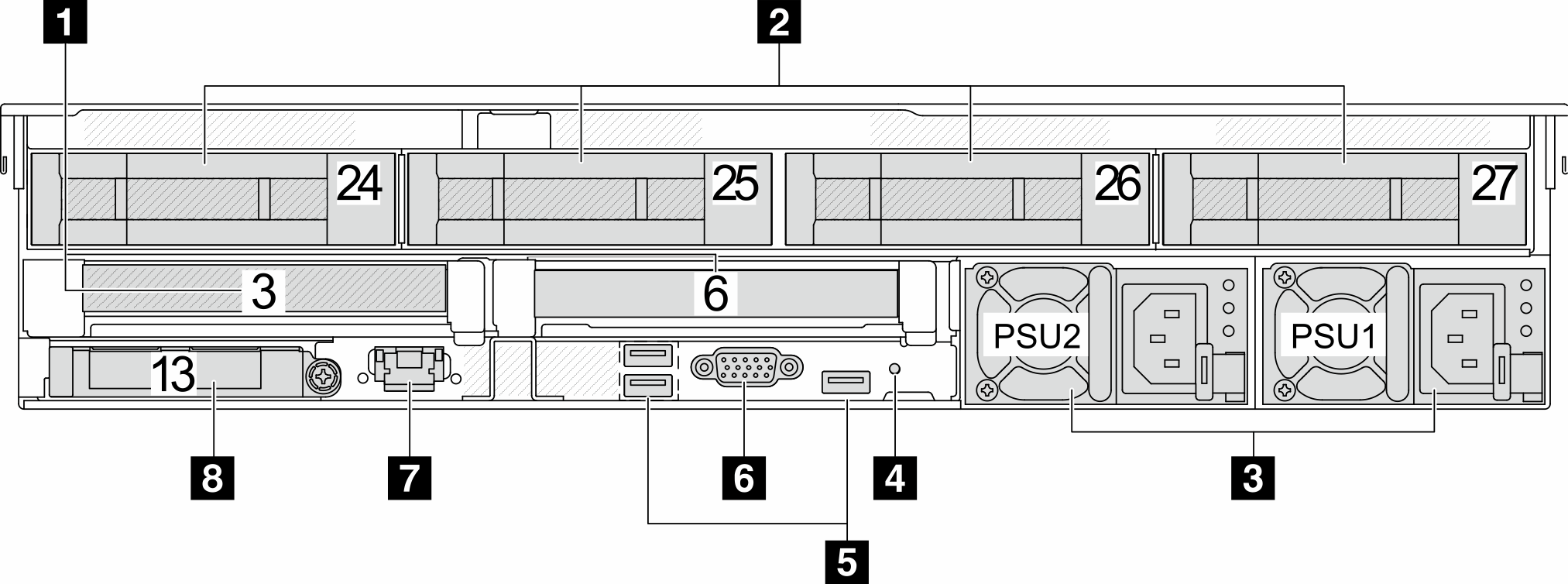
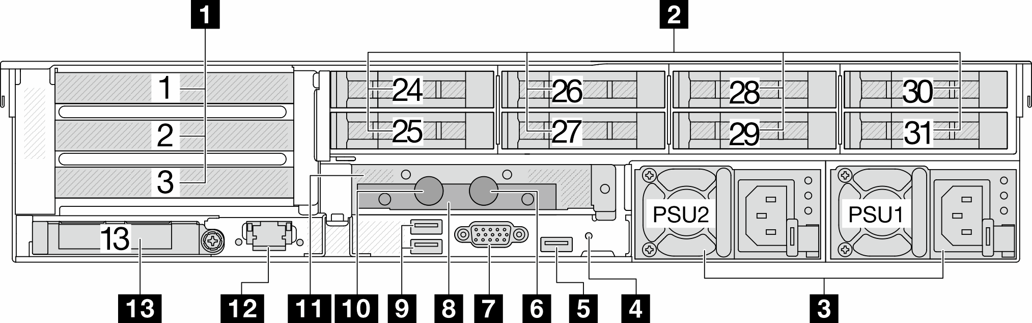
Rear view with eight 2.5-inch rear drive bays and four PCIe slots
| Callout | Callout |
|---|---|
| 1 PCIe slots | 2 Rear 2.5-inch drive bays (8) |
| 3 Power supply units | 4 NMI button |
| 5 USB 3 (5 Gbps) connectors (3) | 6 VGA connector |
| 7 XCC system management port | 8 Ethernet connectors on OCP module (optional) |
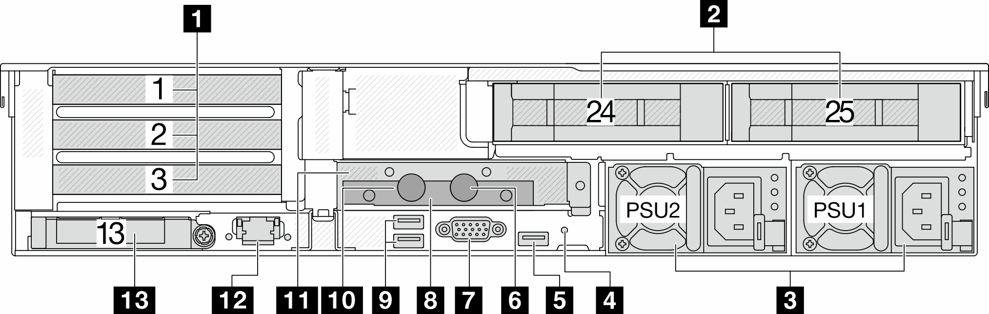
Rear view with two 3.5-inch rear drive bays and four PCIe slots
| Callout | Callout |
|---|---|
| 1 PCIe slots | 2 Rear 3.5-inch drive bays (2) |
| 3 Power supply units | 4 NMI button |
| 5 USB 3 (5 Gbps) connectors (3) | 6 VGA connector |
| 7 XCC system management port | 8 Ethernet connectors on OCP module (optional) |
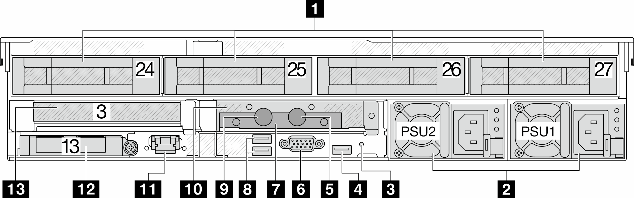
Rear view with four 3.5-inch rear drive bays and two PCIe slots
| Callout | Callout |
|---|---|
| 1 PCIe slots | 2 Rear 3.5-inch drive bays (4) |
| 3 Power supply units | 4 NMI button |
| 5 USB 3 (5 Gbps) connectors (3) | 6 VGA connector |
| 7 XCC system management port | 8 Ethernet connectors on OCP module (optional) |
Rear view with seven PCIe slots and a DWCM
| Callout | Callout |
|---|---|
| 1 PCIe slots | 2 Power supplies |
| 3 NMI button | 4 USB 3 (5 Gbps) connector |
| 5 Outlet hose | 6 VGA connector |
| 7 Hose holder | 8 USB 3 (5 Gbps) connectors |
| 9 Inlet hose | 10 XCC system management port |
| 11 Ethernet connectors on OCP module (optional) |
Rear view with nine PCIe slots and a DWCM
| Callout | Callout |
|---|---|
| 1 PCIe slots | 2 Power supplies |
| 3 NMI button | 4 USB 3 (5 Gbps) connector |
| 5 Outlet hose | 6 VGA connector |
| 7 Hose holder | 8 USB 3 (5 Gbps) connectors |
| 9 Inlet hose | 10 XCC system management port |
| 11 Ethernet connectors on OCP module (optional) |
Rear view with four 2.5-inch rear drive bays, five PCIe slots, and a DWCM
| Callout | Callout |
|---|---|
| 1 PCIe slots | 2 Rear 2.5-inch drive bays (4) |
| 3 Power supplies | 4 NMI button |
| 5 USB 3 (5 Gbps) connector | 6 Outlet hose |
| 7 VGA connector | 8 Hose holder |
| 9 USB 3 (5 Gbps) connectors | 10 Inlet hose |
| 11 XCC system management port | 12 Ethernet connectors on OCP module (optional) |
Rear view with eight 2.5-inch rear drive bays, three PCIe slots, and a DWCM
| Callout | Callout |
|---|---|
| 1 PCIe slots | 2 Rear 2.5-inch drive bays (8) |
| 3 Power supplies | 4 NMI button |
| 5 USB 3 (5 Gbps) connector | 6 Outlet hose |
| 7 VGA connector | 8 Hose holder |
| 9 USB 3 (5 Gbps) connectors | 10 Inlet hose |
| 11 1FH riser cage for DWCM | 12 XCC system management port |
| 13 Ethernet connectors on OCP module (optional) |
Rear view with two 3.5-inch rear drive bays, three PCIe slots, and a DWCM
| Callout | Callout |
|---|---|
| 1 PCIe slots | 2 Rear 3.5-inch drive bays (2) |
| 3 Power supplies | 4 NMI button |
| 5 USB 3 (5 Gbps) connector | 6 Outlet hose |
| 7 VGA connector | 8 Hose holder |
| 9 USB 3 (5 Gbps) connectors | 10 Inlet hose |
| 11 1FH riser cage for DWCM | 12 XCC system management port |
| 13 Ethernet connectors on OCP module (optional) |
Rear view with four 3.5-inch rear drive bays, one PCIe slot, and a DWCM
| Callout | Callout |
|---|---|
| 1 PCIe slots | 2 Rear 3.5-inch drive bays (4) |
| 3 Power supplies | 4 NMI button |
| 5 USB 3 (5 Gbps) connector | 6 Outlet hose |
| 7 VGA connector | 8 Hose holder |
| 9 USB 3 (5 Gbps) connectors | 10 Inlet hose |
| 11 1FH riser cage for DWCM | 12 XCC system management port |
| 13 Ethernet connectors on OCP module (optional) |
Rear components overview
PCIe slots
The PCIe slots are on the rear or front of the server, and your server supports up to 12 PCIe slots. For more information, see PCIe slots and PCIe adapters.
Hot-swap drives and drive bays
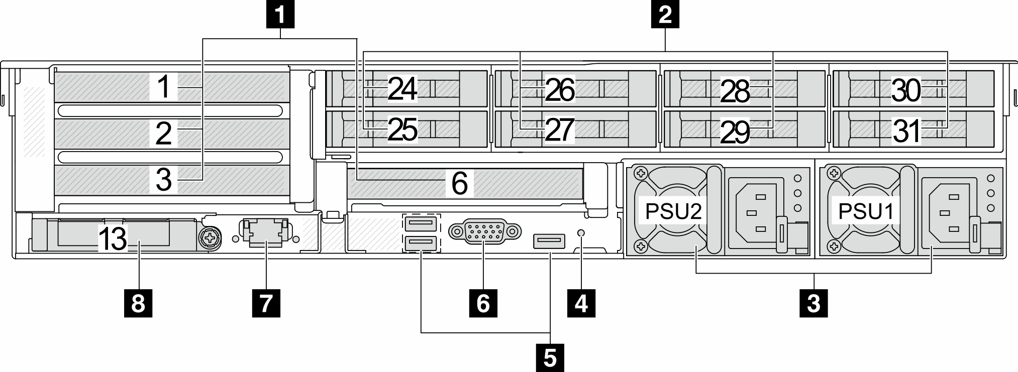
The drive bays on the front and rear of your server are designed for hot-swap drives. The number of the installed drives in your server varies by model. When you install drives, follow the order of the drive bay numbers.
The EMI integrity and cooling of the server are protected by having all drive bays occupied. Vacant drive bays must be occupied by drive fillers.
Power supply units
The hot-swap redundant power supply units help you avoid significant interruption to the operation of the system when a power supply unit fails. You can purchase a power supply option from Lenovo and install the power supply unit to provide power redundancy without turning off the server.
On each power supply unit, there are three status LEDs near the power cord connector. For information about the LEDs, see Power supply LEDs.
USB 3 (5 Gbps) connectors
The USB 3.2 Gen 1 (5 Gbps) connectors are direct connect interfaces (DCIs) for debugging, which can be used to attach a USB-compatible device, such as a USB keyboard, USB mouse, or USB storage device.
VGA connector
The VGA connectors on the front and rear of the server can be used to attach a high-performance monitor, a direct-drive monitor, or other devices that use a VGA connector.
XCC system management port
The server has a 1 GB RJ-45 connector dedicated to Lenovo XClarity Controller (XCC) functions. Through the system management port, you can access the Lenovo XClarity Controller directly by connecting your laptop to the management port using an Ethernet cable. Make sure that you modify the IP settings on the laptop so that it is on the same network as the server default settings. A dedicated management network provides additional security by physically separating the management network traffic from the production network.
Ethernet connectors
Figure 1. OCP module (two connectors) 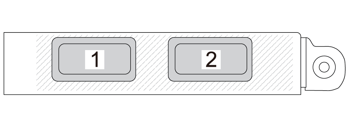 | Figure 2. OCP module (four connectors) 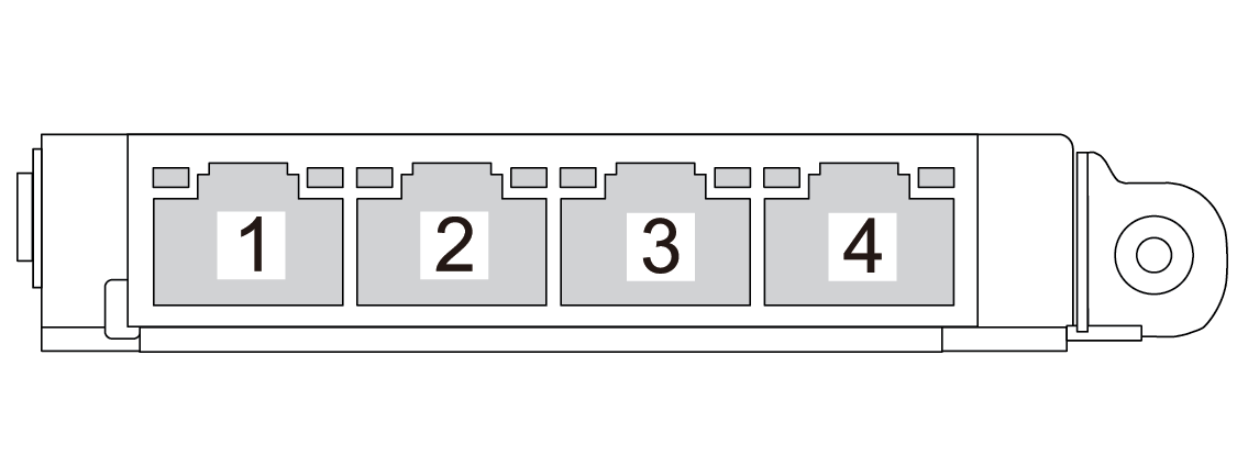 |
The OCP module provides two or four extra Ethernet connectors for network connections. By default, any of the connectors on the OCP module can function as a shared management connector.
Inlet and outlet hoses
The Direct Water Cooling Module (DWCM) spreads two hoses out to connect to the manifolds. The inlet hose conveys warm water from the facility to the cold plates to cool down the processors, and the outlet hose conducts hot water out of the DWCM to realize system cooling.