System-board-assembly layout
This section provides information about the connectors, switches, and jumpers that are available on the system board assembly.
The following illustration shows the layout of the system board assembly that contains the firmware and RoT security module, system I/O board, and processor board.
Figure 1. System-board-assembly layout
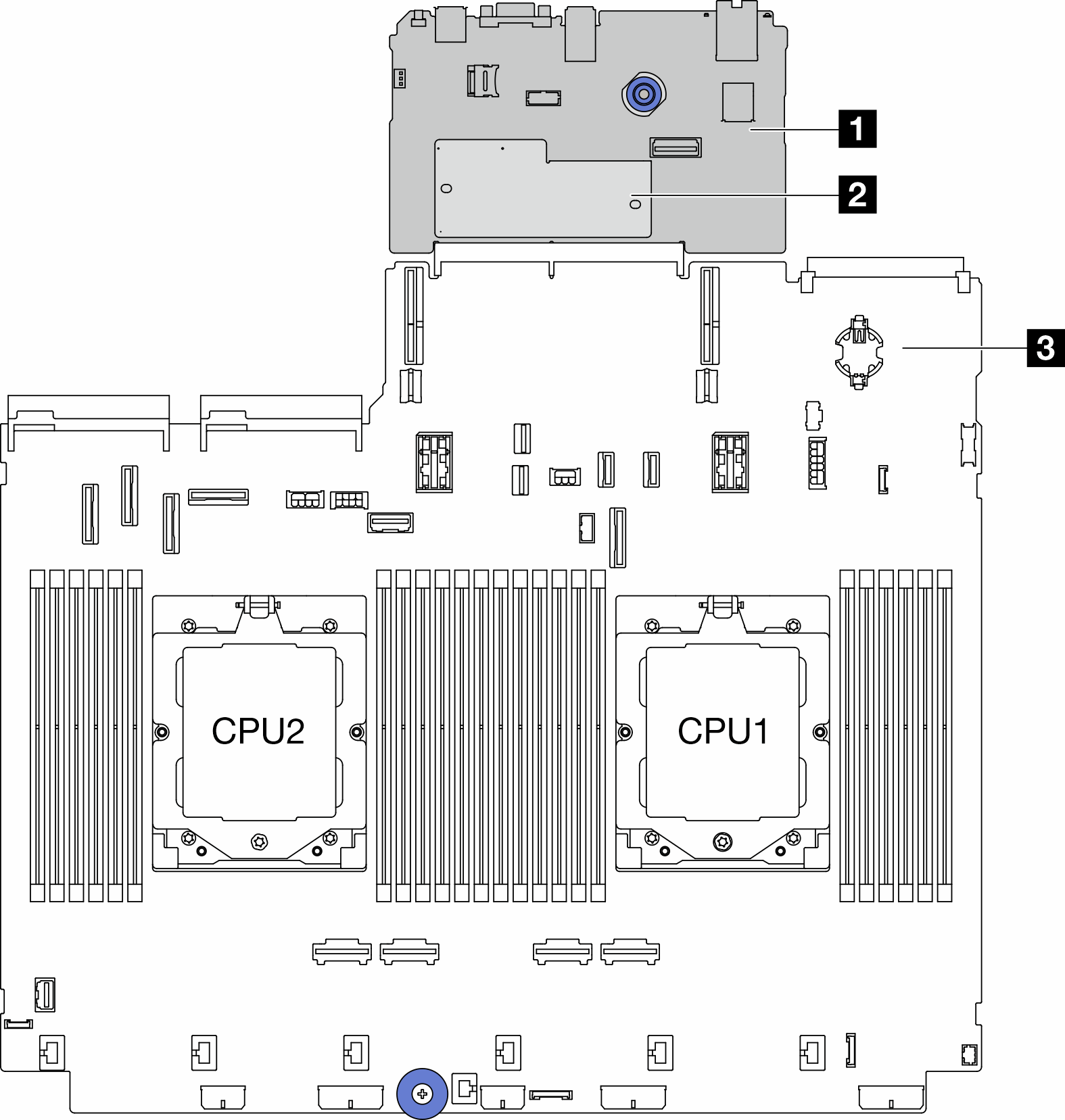
| 1 System I/O board | 2 Firmware and RoT security module | 3 Processor board |
For information about the LEDs that are available on the system board assembly, see:
Give documentation feedback