E/A-Baugruppe an der Vorderseite
Verwenden Sie diesen Abschnitt, um die Kabelführung für vordere E/A-Baugruppen zu verstehen.
Anmerkung
In der Abbildung wird das Verkabelungsszenario für Servermodelle mit zwölf 3,5‑Zoll-Laufwerkpositionen an der Vorderseite dargestellt. Die Position der Anschlüsse an der Vorderseite des Servers variiert je nach Modell. Detaillierte Informationen zur Position der E/A-Komponenten an der Vorderseite für verschiedene Modelle finden Sie im Abschnitt Vorderansicht.
Abbildung 1. Front I/O assembly cable routing
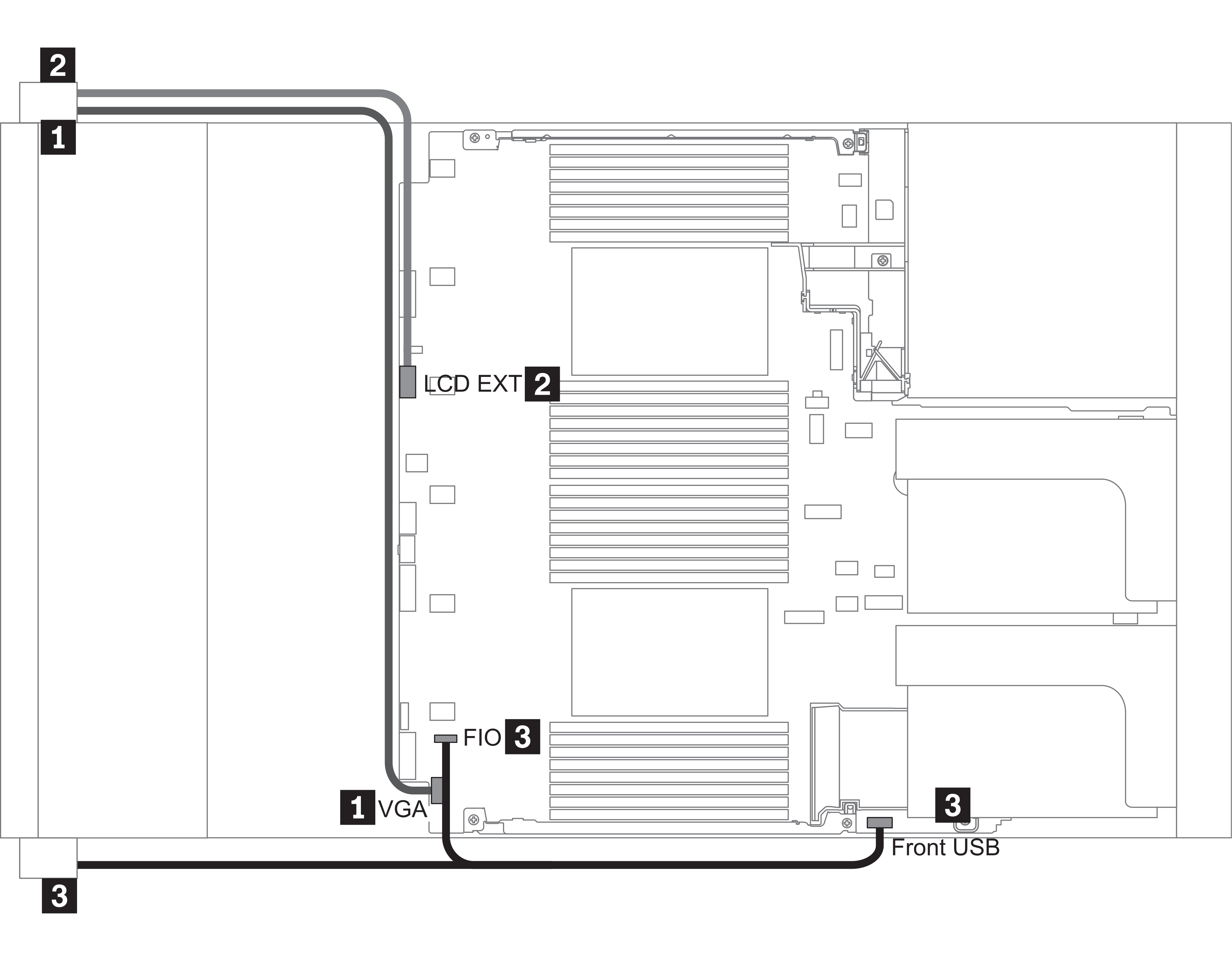
| From | To |
|---|---|
| 1 VGA cable on the left rack latch | VGA connector on the system board |
| 2 External diagnostics cable on the left rack latch | External LCD connector on the system board |
| 3 Front USB and panel cable on the right rack latch | Front I/O and front USB connectors on the system board |
Feedback geben