正面 I/O 组合件
按本部分的说明了解正面 I/O 组合件的线缆布放。
注
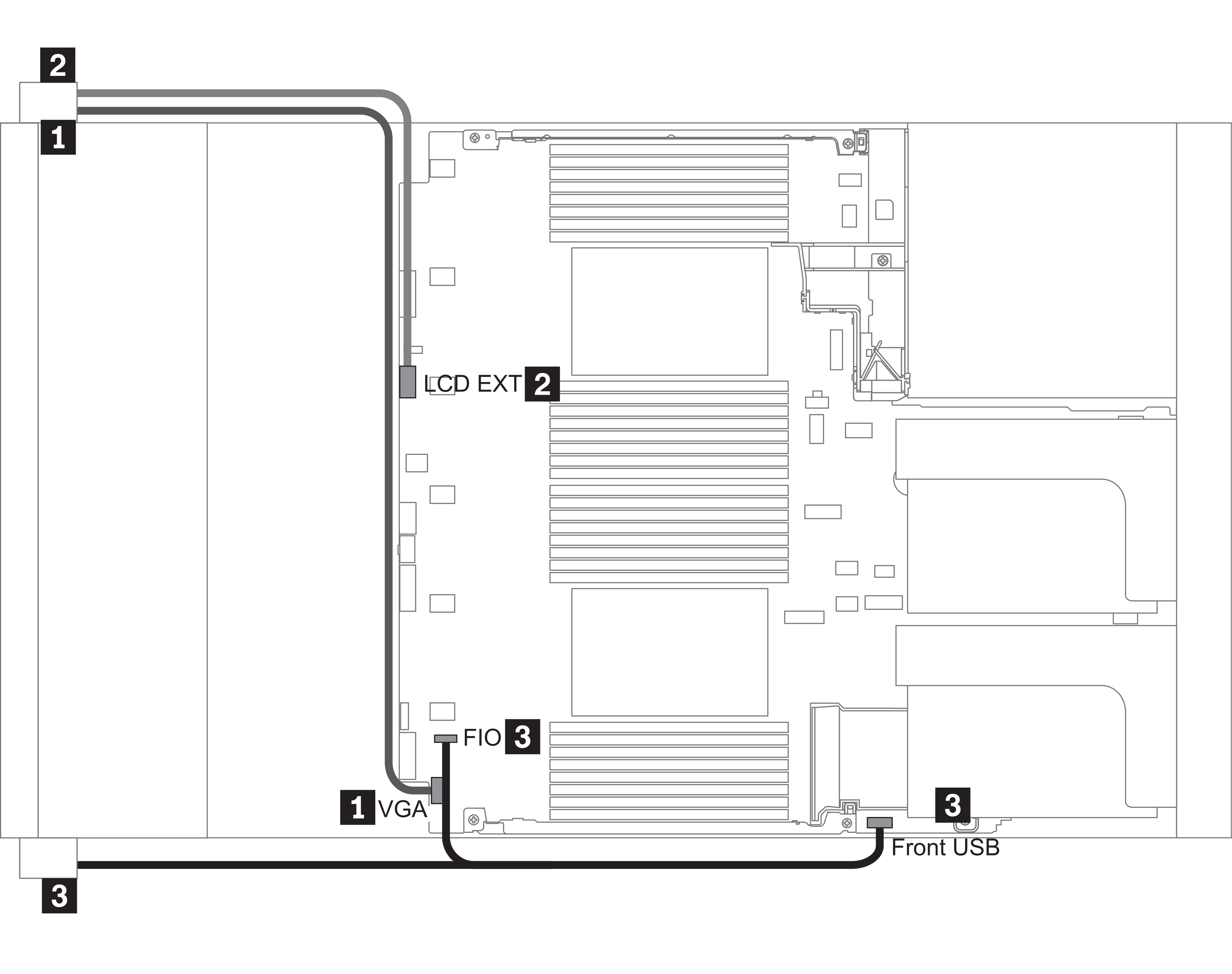
此插图显示了配备十二个 3.5 英寸正面硬盘插槽的服务器型号的布线方案。各接口在服务器正面的位置取决于型号。有关不同型号的正面 I/O 组件的详细位置,请参阅前视图。
图 1. Front I/O assembly cable routing


| From | To |
|---|---|
| 1 VGA cable on the left rack latch | VGA connector on the system board |
| 2 External diagnostics cable on the left rack latch | External LCD connector on the system board |
| 3 Front USB and panel cable on the right rack latch | Front I/O and front USB connectors on the system board |
提供反馈