Install a GPU adapter
Follow instructions in this section to install a GPU adapter.
About this task
Read Installation Guidelines and Safety inspection checklist to ensure that you work safely.
Touch the static-protective package that contains the component to any unpainted metal surface on the server; then, remove it from the package and place it on a static-protective surface.
Depending on the specific type, your GPU adapter might look slightly different from the illustrations in this section.
Follow the additional instructions in any documentation that comes with your GPU adapter.
The server is equipped with a GPU adapter.
The UEFI firmware version is U8E128A or later.
The DisplayPort ports on the Nvidia A40 GPU are not supported when used in the ThinkSystem SR670 V2.
Procedure
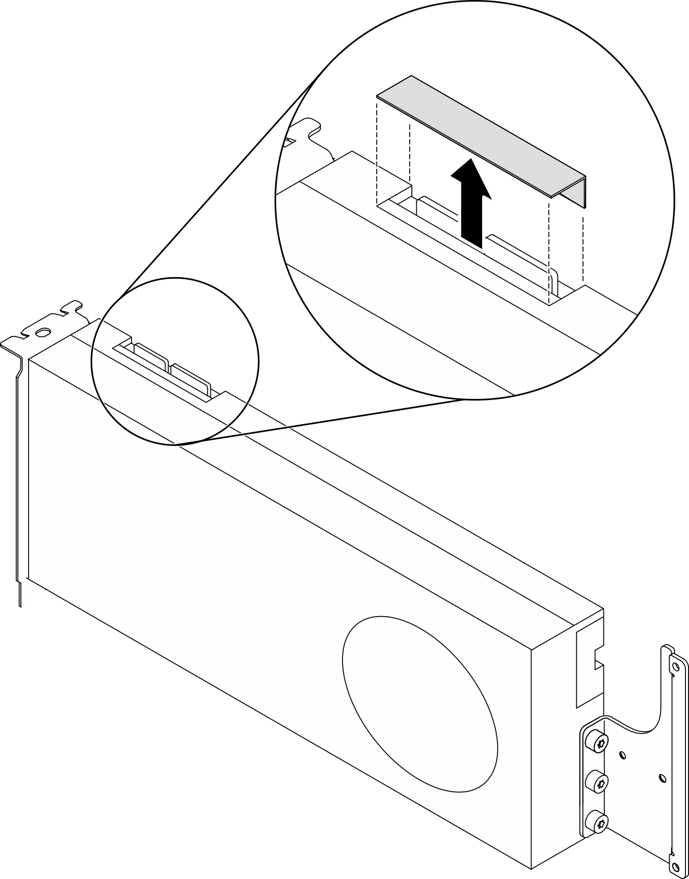
- (Optional) If a GPU adapter link bridge is to be installed, remove the link connector cover from the GPU. Keep the link connector cover in case it is needed in the future.NoteDepending on the configuration, there may be one or three GPU adapter link bridges on the GPU. When linking a GPU pair, all link connectors on the GPUs must be linked.Figure 1. Removing the link connector cover from the GPU
- Install the GPU adapter.NoteIf the PCIe slot is covered with a slot bracket, remove the bracket from the chassis first.Figure 2. Installing a GPU adapter
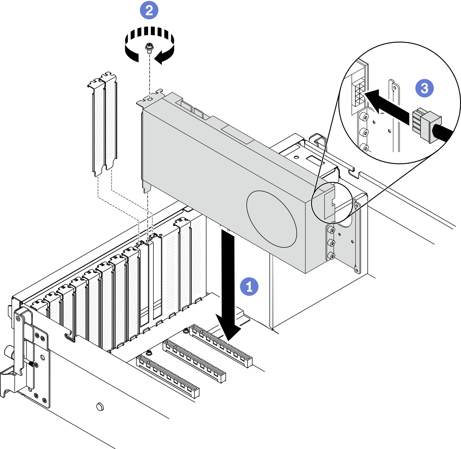
 Align the GPU adapter with the PCIe slot on the chassis. Then, carefully press both ends of the GPU adapter straight into the slot until it is securely seated.NoteMake sure that the rear end of each adapter is inserted into the slot next to the two imprinted arrows on the chassis.
 Fasten the GPU adapter retention screw.
 Connect the GPU adapter power cable to the GPU adapter. Refer to the GPU adapter and system board GPU power connector mapping table. For more details on GPU power connectors on system board, see System-board connectors.
Table 1. GPU adapter and system board GPU power connector mapping table Item Numbering GPU adapter
(PCIe slot)
1
(Slot 3)
2
(Slot 4)
3
(Slot 5)
4
(Slot 6)
5
(Slot 7)
6
(Slot 8)
7
(Slot 9)
8
(Slot 10)
System board GPU power connector 1 2 3 4 5 6 7 8
After you finish
To install the GPU adapter link bridge, see Install a GPU adapter link bridge.
Complete the parts replacement. See Complete the parts replacement.
Demo video