The SXM GPU Model front view
This section contains information about the controls, LEDs, and connectors on the front of the SXM GPU Model server.
Figure 1. Front view of the SXM GPU Model
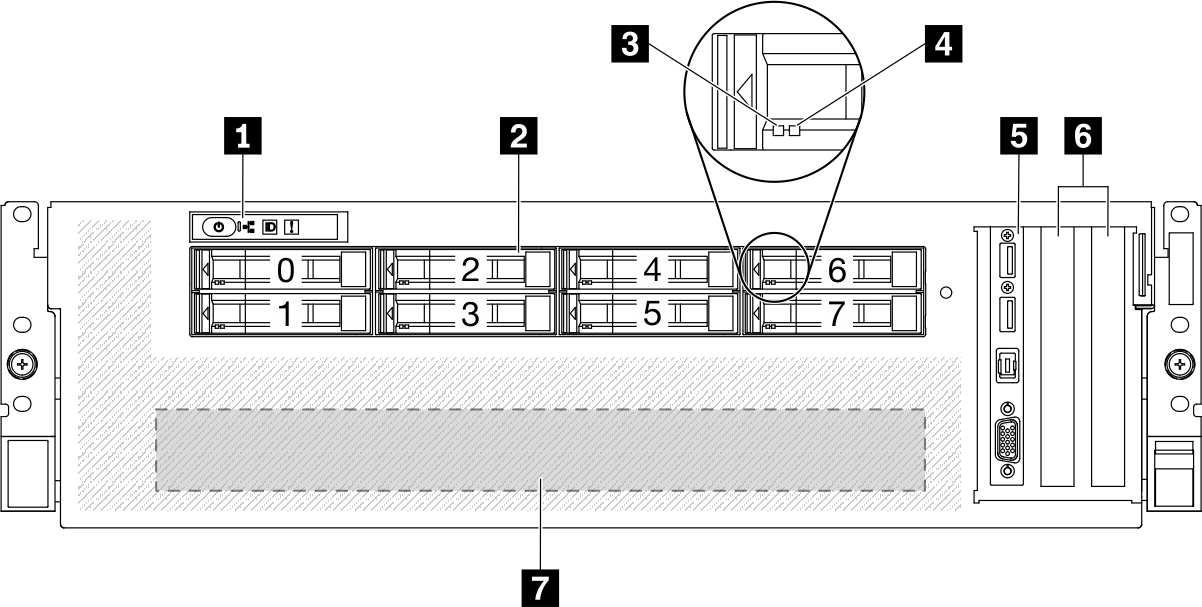
| 1 Front panel | 5 Front I/O module |
| 2 2.5-inch drive bays (bay 0 to 7) | 6 PCIe slots 1-2 |
| 3 Drive activity LED (green) | 7 GPU-L2A assembly |
| 4 Drive status LED (yellow) |
1 Front panel
For more information about the front panel, see Front panel.
2 2.5-inch drive bays (bay 0 to 7)
Install 2.5-inch drives to these bays. See Install a 2.5-inch hot-swap drive.
3 Drive activity LED (green)
Each hot-swap drive comes with an activity LED. When this LED is flashing, it indicates that the drive is in use.
4 Drive status LED (yellow)
The drive status LED indicates the following status:
The LED is lit: the drive has failed.
The LED is flashing slowly (once per second): the drive is being rebuilt.
The LED is flashing rapidly (three times per second): the drive is being identified.
5 Front I/O module
For more information about the front I/O module, see Front I/O module.
6 PCIe slots 1-2
Install PCIe adapters, particularly network adapters to these slots. These PCIe slots support the following configuration:
PCIe slot 1-2, PCIe x16, FH/HL
7 GPU-L2A assembly
Install the GPU-L2A assembly in this space. A GPU-L2A assembly consists of the Lenovo Neptune® liquid-to-air (L2A) hybrid cooling module and the SXM GPU board, which contains one of the following:
One set of HGX A100 40GB 400W 4-GPU Board
One set of HGX A100 80GB 500W 4-GPU Board
AttentionWhen the HGX A100 80GB 500W 4-GPU Board is installed and if the ambient temperature is above 30°C, the GPUs may be instructed by the system to enter an emergency power reduction state whereby GPU performance will be impacted.
Give documentation feedback