Rear view
The rear of the server provides access to several components, including the power supplies, PCIe adapters, serial port, and Ethernet port.
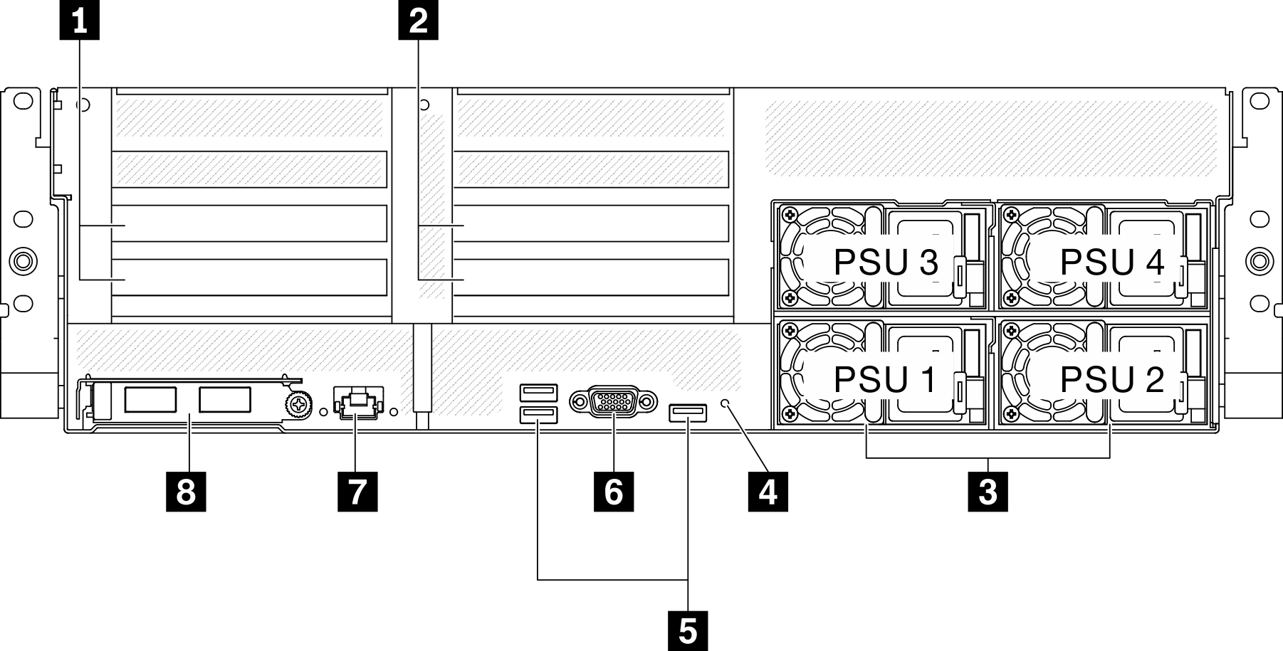
| 1 PCIe riser 1 (PCIe slot 15-16) | 5 USB 3.2 Gen 1 connectors (total of three connectors) |
| 2 PCIe riser 2 (PCIe slot 20-21) | 6 VGA connector |
| 3 Power supply units | 7 System management 1 GB RJ-45 connector dedicated to Lenovo XClarity Controller functions. |
| 4 NMI button | 8 OCP 3.0 Ethernet adapter |
1 / 2 PCIe riser
Install PCIe adapters into these risers. See the following table for PCIe slots corresponding to the risers.
| PCIe riser | PCIe slot (PCI Express 4.0 x16, FH/FL) |
|---|---|
| 1 PCIe riser 1 | Slot 15: PCI Express 4.0 x16, FH/HL |
Slot 16: PCI Express 4.0 x16 / x8, FH/HL | |
| 2 PCIe riser 2 | Slot 20: PCI Express 4.0 x16, FH/HL |
Slot 21: PCI Express 4.0 x16 / x8, FH/HL |
3 Power supply units
Install power supply units to these bays, connect them to power cords. Make sure the power cords are connected properly. Following are the power supplies supported by this system:
2600-watt Titanium, input power 200-240 VAC
2400-watt Platinum, input power 200-240 VAC
1800-watt Platinum, input power 200-240 VAC
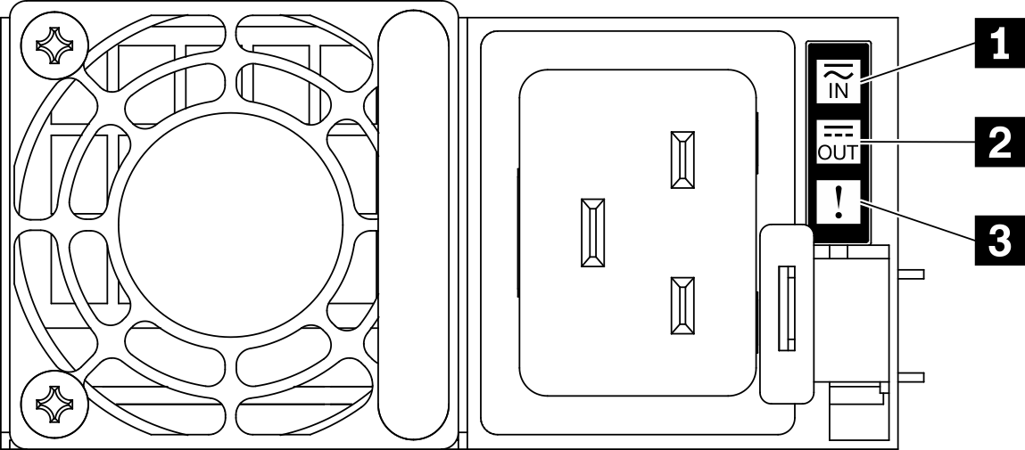
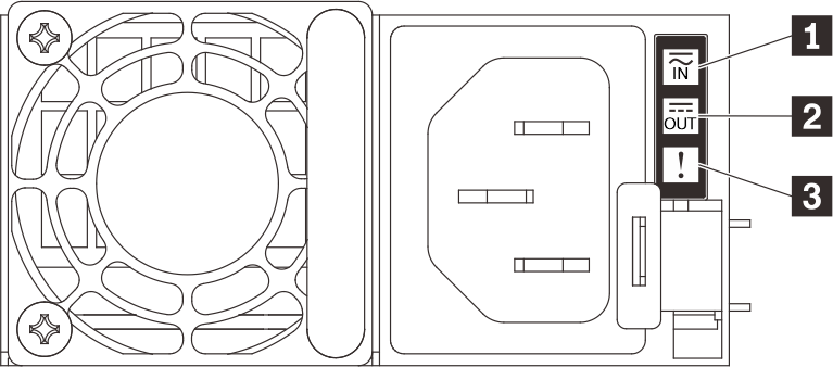
| LED | Description |
|---|---|
| 1 Input status | The input status LED can be in one of the following states:
|
| 2 Output status | The output status LED can be in one of the following states:
|
| 3 Fault LED |
|
5 USB 3.2 Gen 1 connector
There are three USB 3.2 Gen 1 connectors on the rear of the server. Connect a USB device, such as a mouse, keyboard, or other devices, to either of these connectors.
6 VGA connector
Connect a monitor to this connector.
7 System management port
The server has a 1 GB RJ-45 connector dedicated to Lenovo XClarity Controller functions. Through the management port, you can access the Lenovo XClarity Controller directly by connecting your laptop to the management port using an Ethernet cable. Make sure that you modify the IP settings on the laptop so that it is on the same network as the server default settings. A dedicated management network provides additional security by physically separating the management network traffic from the production network.
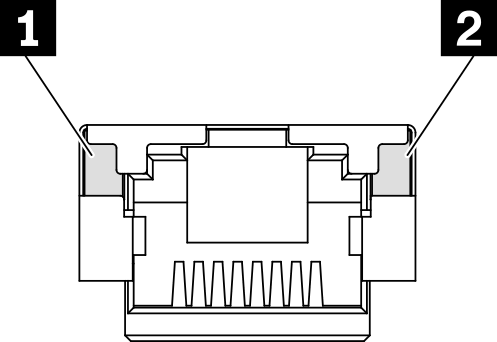
| LED | Description |
|---|---|
| 1 1 GB RJ-45 Ethernet port link LED | Use this green LED to distinguish the network connectivity status:
|
| 2 1 GB RJ-45 Ethernet port activity LED | Use this green LED to distinguish the network activity status:
|
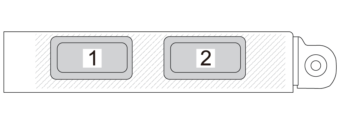
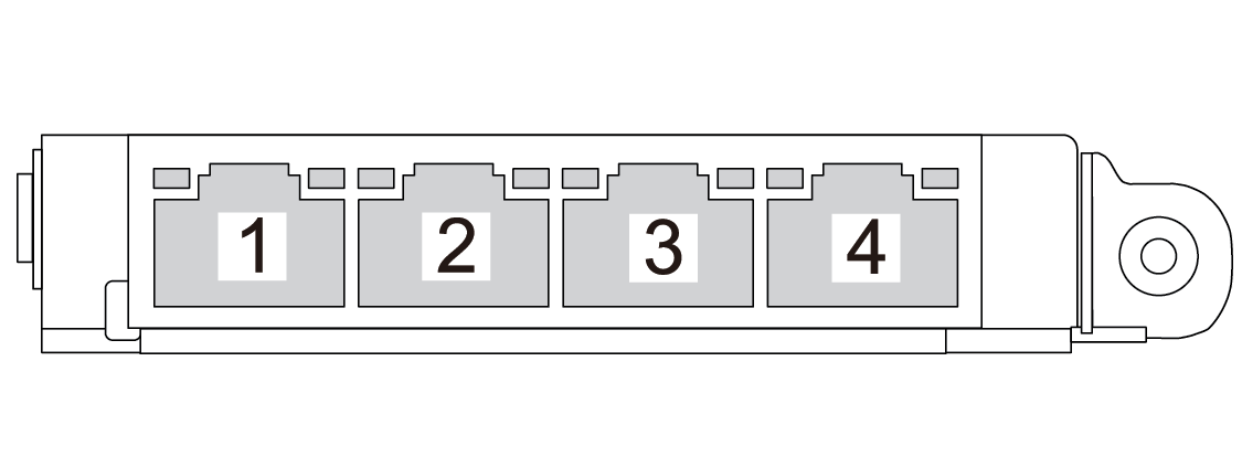
8 OCP 3.0 Ethernet adapter
The OCP 3.0 Ethernet adapter provides a group of two or four Ethernet connectors on OCP 3.0 Ethernet adapter for network connections.