Installation du module de plaque froide GPU B200 arrière
Suivez les instructions de la présente section pour installer le module de plaque froide GPU B200 arrière. La procédure doit être exécutée par un technicien qualifié.
À propos de cette tâche
- Lisez Conseils d’installation et Liste de contrôle d’inspection de sécurité pour vous assurer que vous travaillez en toute sécurité.
- Mettez l’emballage antistatique contenant le composant contre une zone métallique non peinte du serveur, puis déballez et posez le composant sur une surface de protection antistatique.
- Un tournevis dynamométrique est disponible sur demande si vous n’en avez pas à portée de main.
- Tournevis à tête T15 Torx
- Rallonge Torx T15 200mm
- Tournevis cruciforme n°1
- Tournevis cruciforme n°2
- Tampon de nettoyage à l’alcool
- PCM B200
- B200 SXM6 PAD-1
- B200 SXM6 PAD-2
- Kit de support d’expédition F&R GPU B200
- Avant de remplacer le tampon de mastic ou le matériau à changement de phase, nettoyez délicatement la surface du matériel à l’aide d’un chiffon doux imbibé d’alcool.
- Maintenez le tampon de mastic/le PCM avec précautions afin de ne pas le déformer. Assurez-vous qu’aucun trou de vis ou orifice n’est obstrué par le tampon de mastic/PCM.
- N’utilisez pas de tampon de mastic/PCM périmé. Vérifiez la date de péremption sur l’emballage du tampon de mastic ou du PCM. Si les tampons de mastic/le PCM ont dépassé la date limite d’utilisation, achetez-en de nouveaux afin de les remplacer correctement.
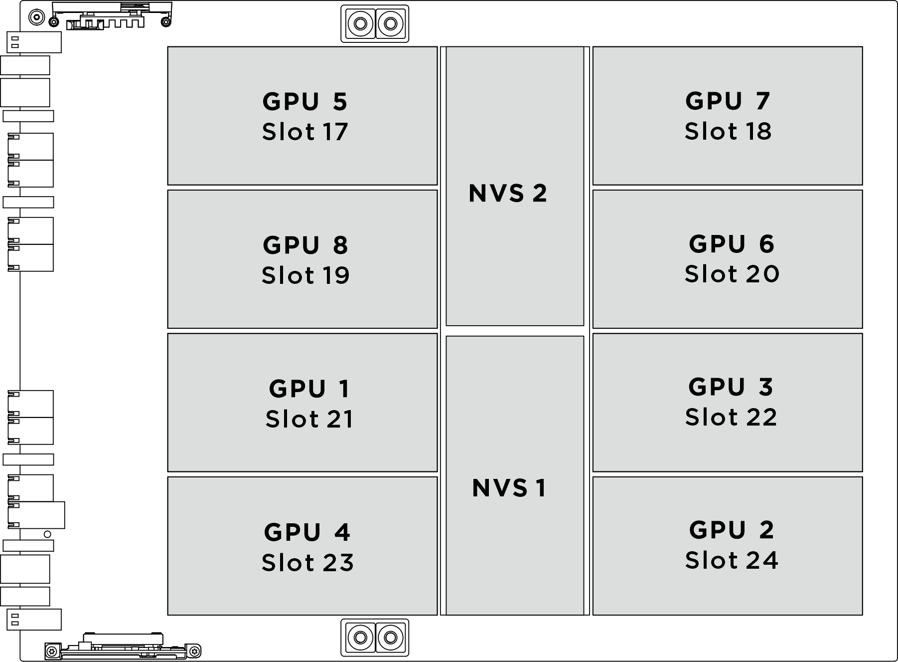
| Socket GPU physique | Numérotation des emplacements dans XCC | Numéro logique dans nvidia-smi |
|---|---|---|
GPU 1 | Emplacement 21 | 4 |
GPU 2 | Emplacement 24 | 7 |
GPU 3 | Emplacement 22 | 5 |
GPU 4 | Emplacement 23 | 6 |
GPU 5 | Emplacement 17 | 0 |
GPU 6 | Emplacement 20 | 3 |
GPU 7 | Emplacement 18 | 1 |
GPU 8 | Emplacement 19 | 2 |
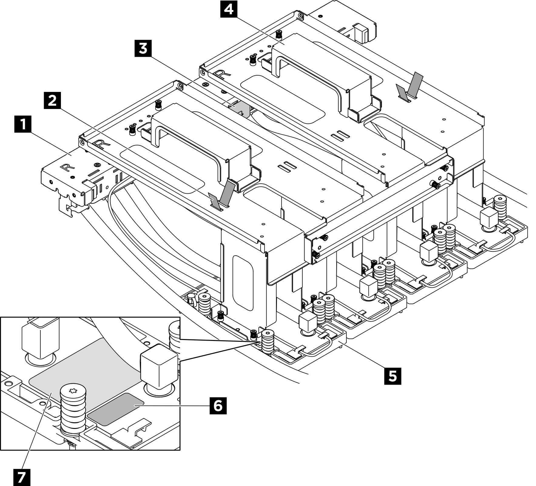
| 1 Collecteur | 2 Collier de serrage |
| 3 Module de détecteur de fuite | 4 Support de transport |
| 5 Plaque froide GPU | 6 Étiquette de numéro d’emplacement GPU |
| 7 Étiquette sur le couple des vis de la plaque froide GPU |
Procédure
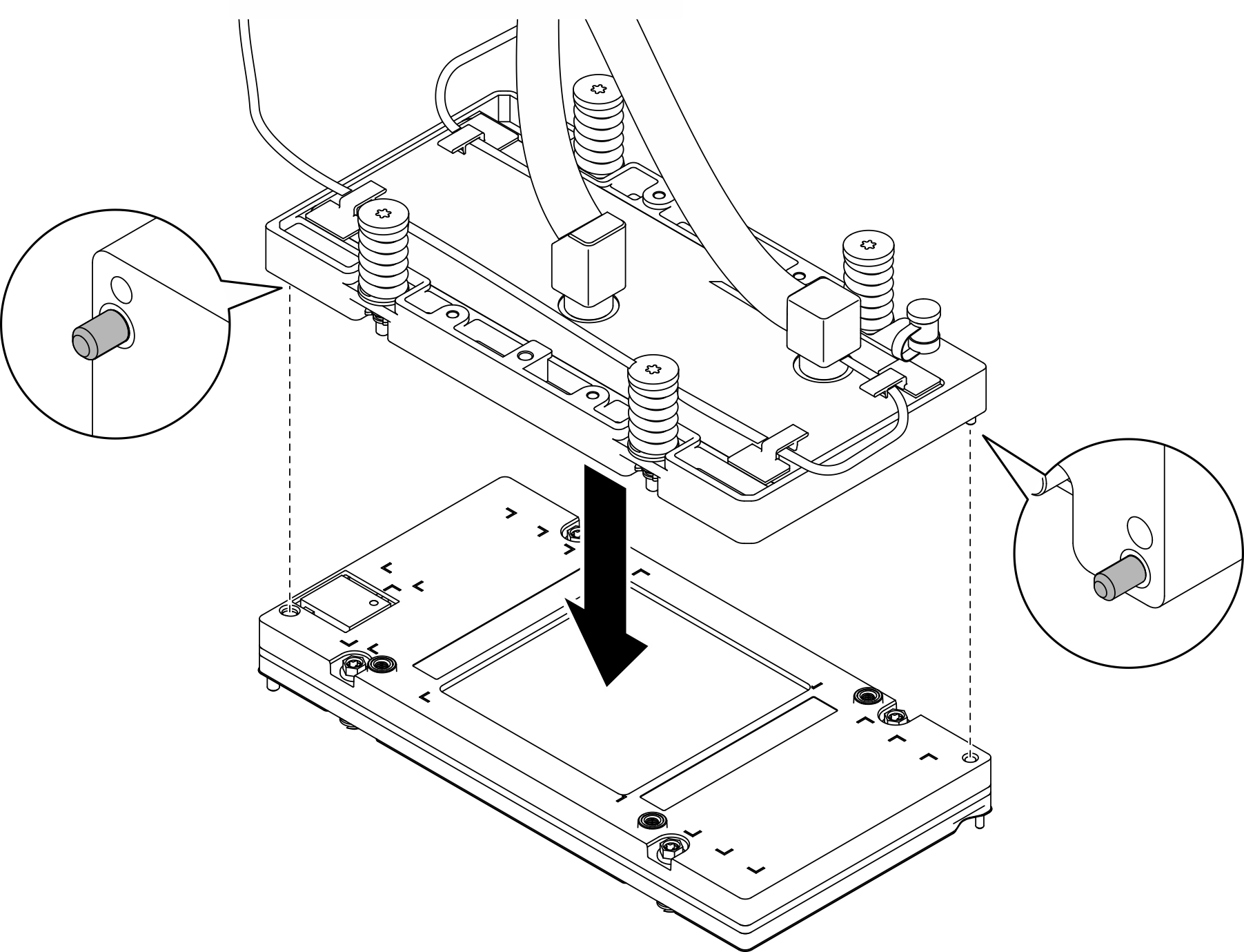
- Remplacez le matériel de modification de phase (PCM) sur le module de plaque froide GPU avant.
 Assurez-vous que le support de transport est fixé au module de plaque froide GPU. Retournez le module et placez-le sur une surface avec la plaque froide orientée vers le haut.
 Appliquez le gabarit PCM sur la plaque froide GPU.
 Retirez le revêtement d’un côté du tampon. Alignez le PCM sur le gabarit et placez-le sur la plaque froide. Retirez le gabarit ; appliquez ensuite une pression du doigt sur toute la surface du PCM pour éliminer l’air emprisonné et laissez agir 1 à 2 minutes jusqu’à ce qu’il soit solidement fixé. Retirez avec précaution le revêtement supérieur restant.
 Répétez l’opération pour remplacer le PCM sur les quatre plaques froides.Avertissement
Il n’est pas possible de réutiliser le PCM.Il faut remplacer le PCM par un neuf à chaque retrait de la boucle d’eau.
Figure 3. Application d’un PCM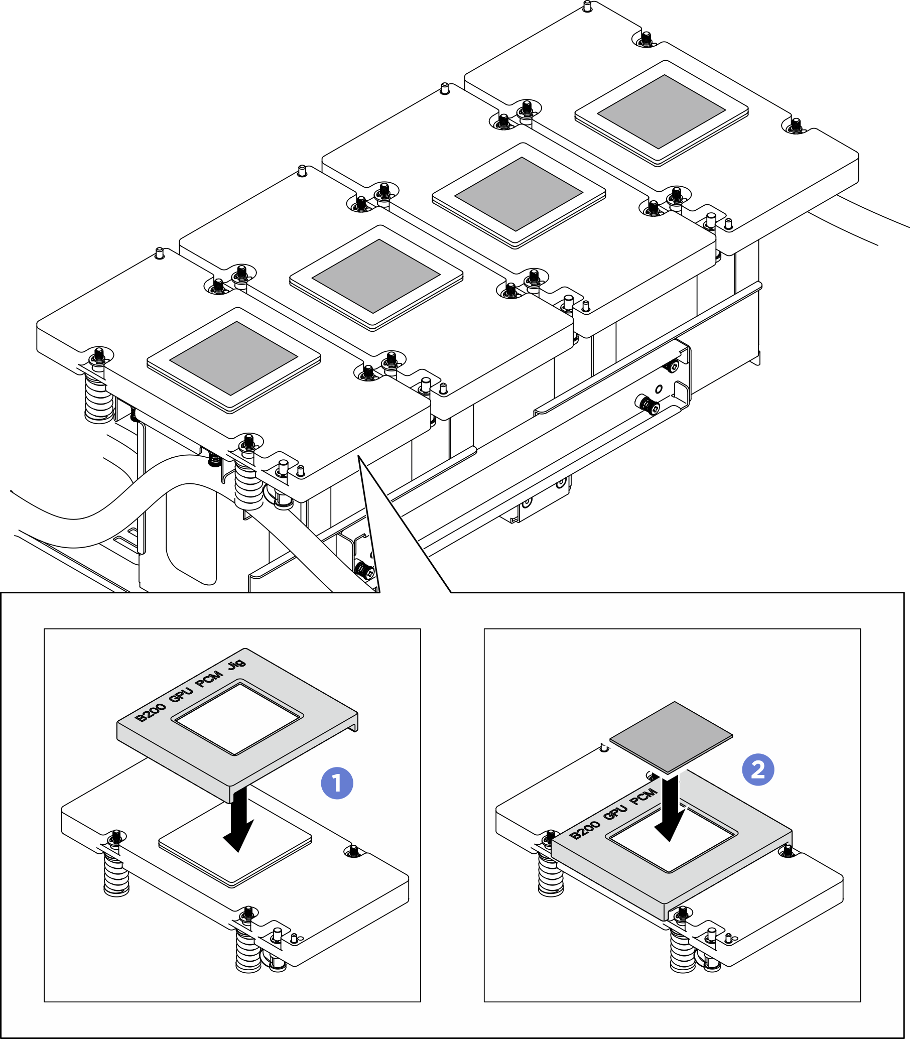
- Remplacez les tampons de mastic (x10) sur le GPU.
- Suivez les instructions d’application du GPU B200 pour appliquer les tampons de mastic.Remarque
- Appliquer les tampons de mastic de B200 SXM6 PAD-1 aux six emplacements indiqués par le numéro 1
- Appliquer les tampons de mastic de B200 SXM6 PAD-1 aux deux emplacements indiqués par le numéro 2
- Appliquer les tampons de mastic de B200 SXM6 PAD-2 aux deux emplacements sur le GPU VR indiqués par les numéros 3 et 4 (couleur grise)
Figure 4. Instructions concernant les tampons de mastic du GPU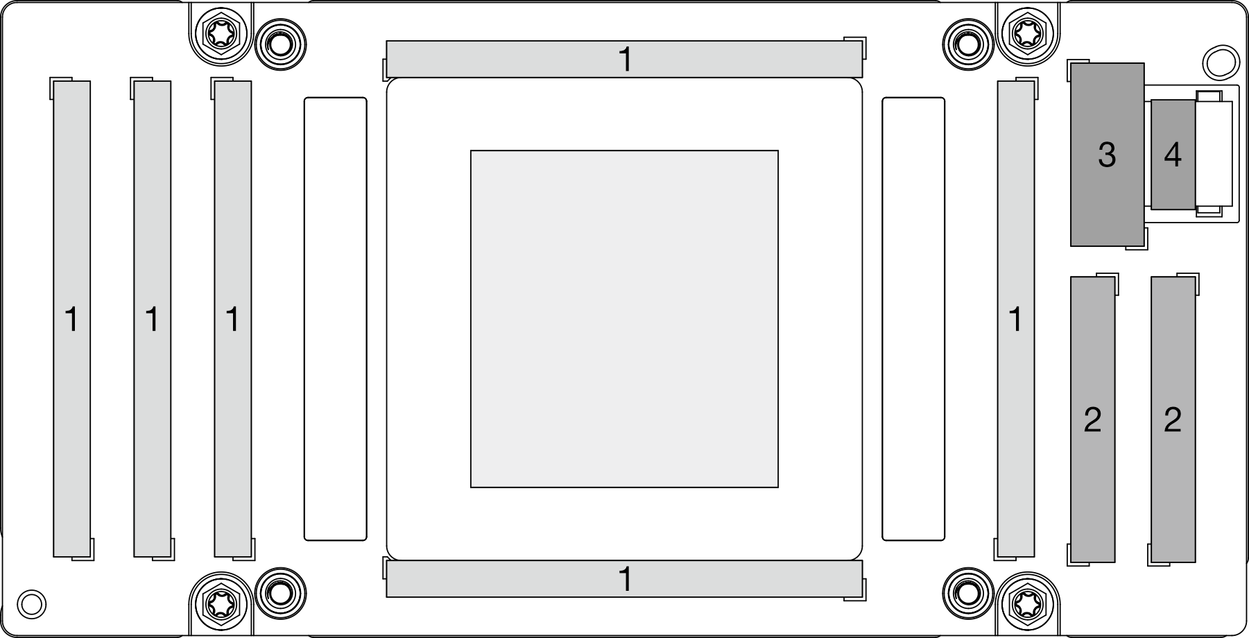
- Retirez le revêtement d’un côté du tampon.
- Assurez-vous d’aligner les deux tampons de mastic de couleur grise sur le VR GPU (1) et les marques ; ensuite, placez les tampons pour couvrir le VR GPU comme illustré et appliquez une légère pression du doigt sur toute la surface des tampons pour assurer leur adhérence. Retirez avec précaution le revêtement supérieur restant.
- Alignez les tampons de mastic sur le GPU ; placez ensuite les tampons sur le GPU et appliquez une légère pression du doigt sur toute la surface des tampons pour assurer l’adhérence. Retirez avec précaution le revêtement supérieur restant.
 Répétez la procédure pour remplacer tous les tampons de mastic des quatre GPU.Avertissement
- Il n’est pas possible de réutiliser le tampon de mastic.Il faut remplacer le tampon de mastic par un neuf à chaque retrait de la boucle d’eau.
Figure 5. Remplacement des tampons de mastic du GPU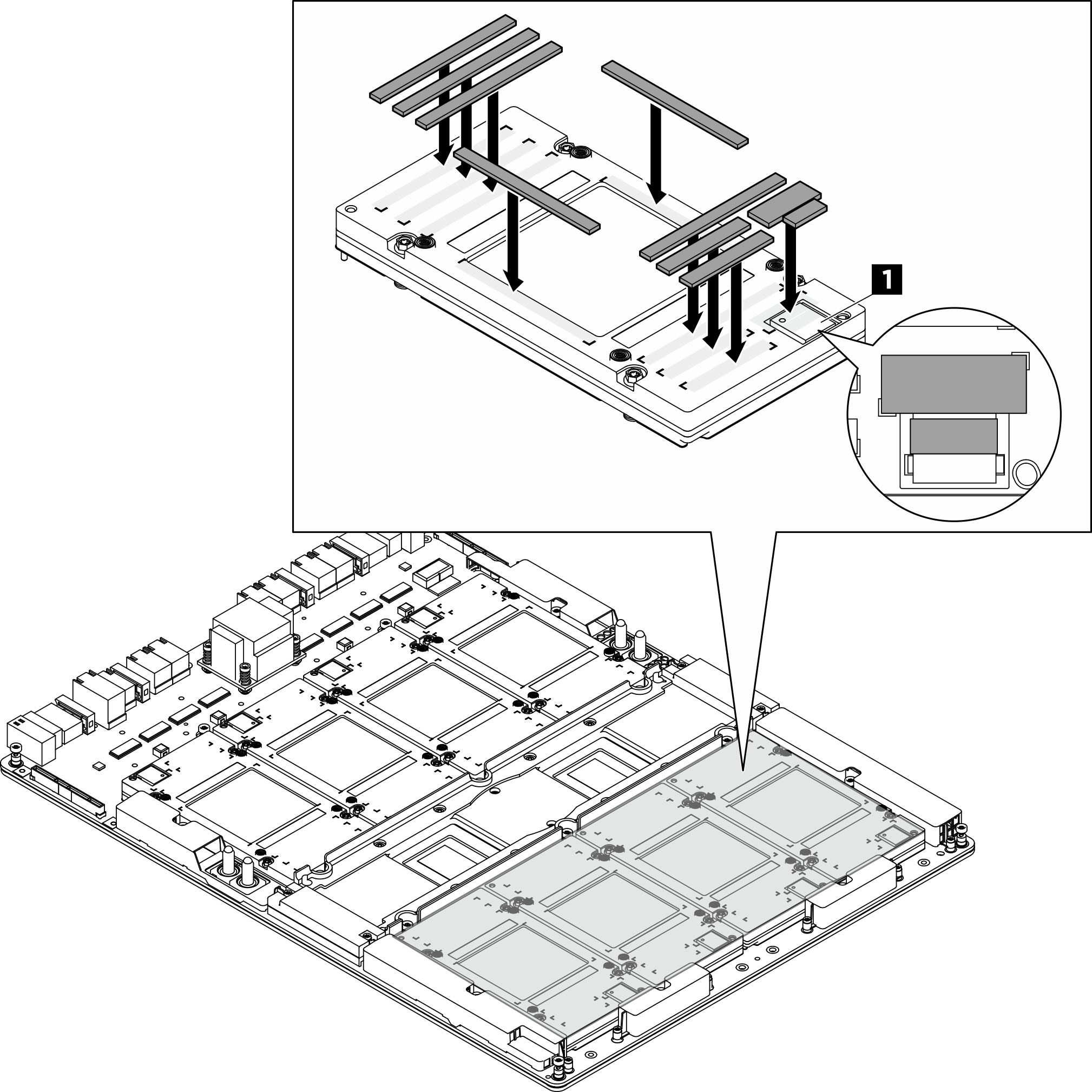
1 VR GPU (recouvrez le VR GPU d’un tampon de mastic)
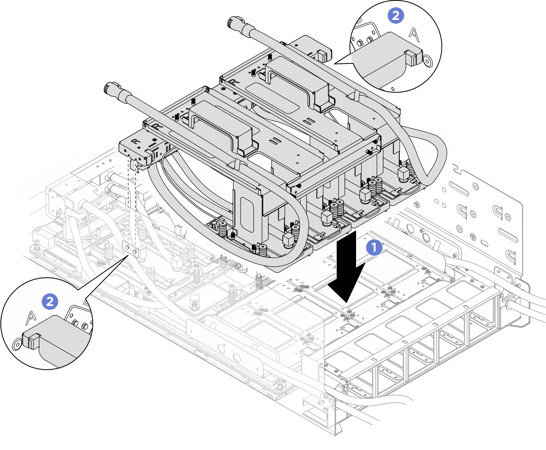
- Installez le module de plaque froide GPU B200 arrière.
- Saisissez le module de plaque froide GPU B200 arrière par les supports de transport ; ensuite, alignez les emplacements de guidage du collecteur sur les broches de guidage et placez délicatement le module de plaque froide sur les quatre GPU arrière.
- Assurez-vous que les fentes de guidage du collecteur sont bien fixées aux broches de guidage du châssis.Figure 6. Installation du module de plaque froide GPU B200 arrière
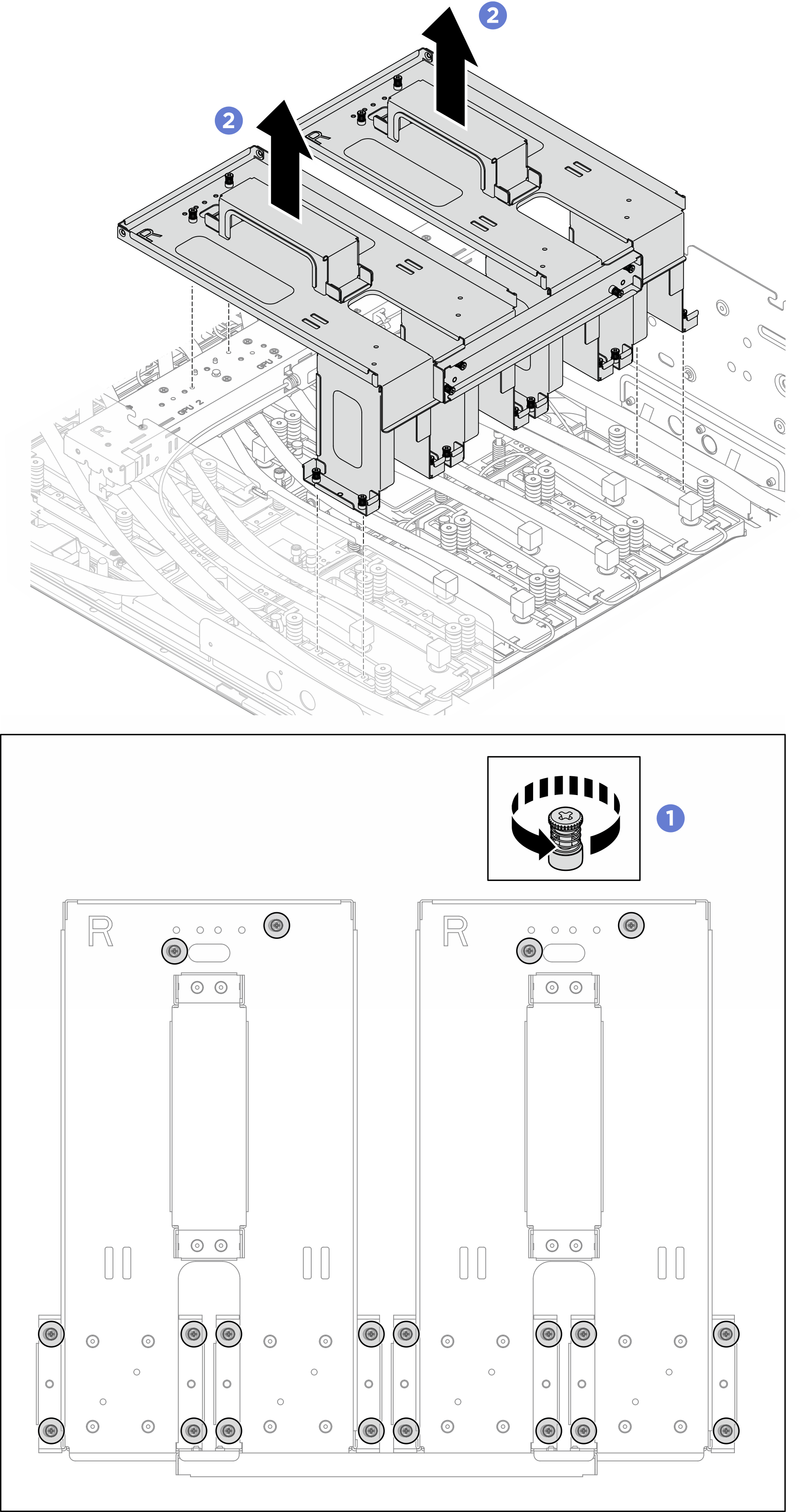
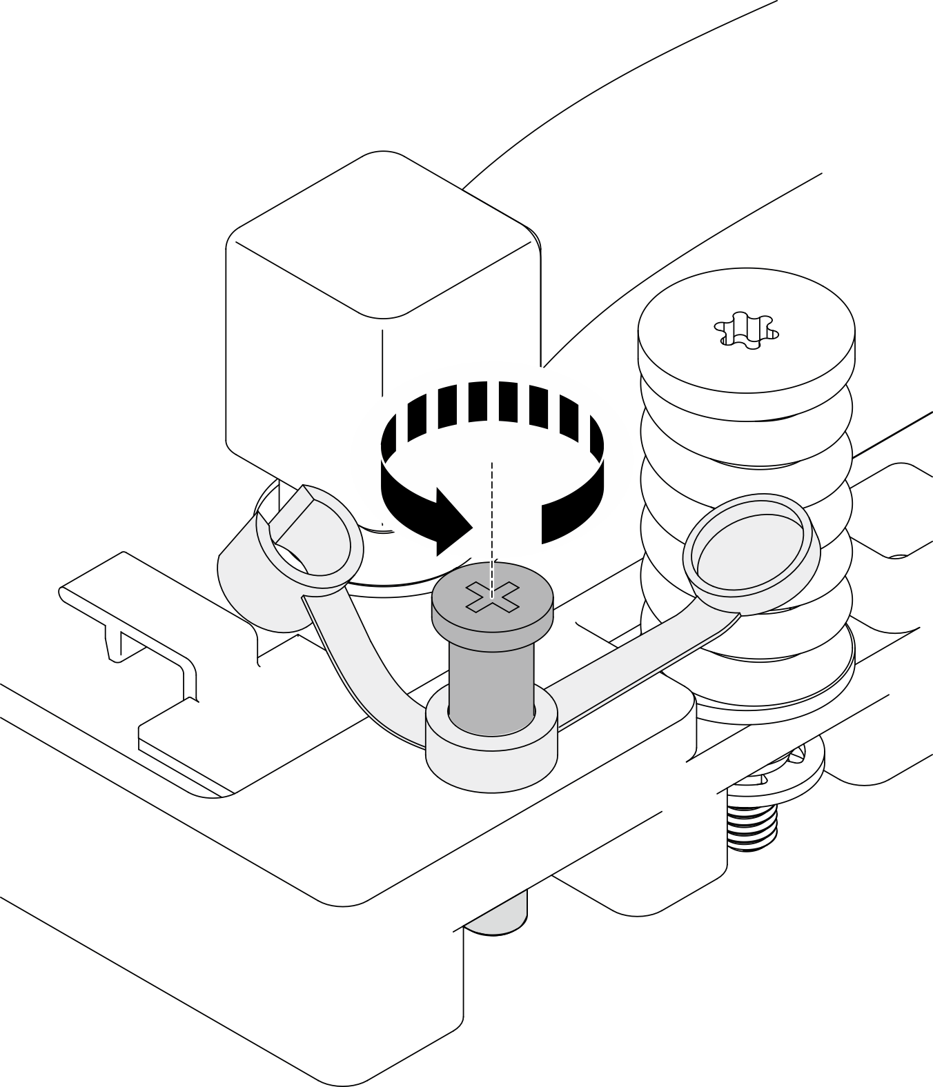
- Retirez les supports de transport.
- Desserrez les vingt vis imperdables qui fixent les deux supports de transport au module de plaque froide GPU B200 avant.
- Soulevez les supports de transport hors du châssis.Figure 7. Retrait des supports de transport
- Ajustez la plaque froide jusqu’à ce que les deux broches de guidage soient bien en place dans les trous de guidage du GPU. Répétez l’opération pour ajuster les quatre plaques froides.Figure 8. Réglage des plaques froides GPU
- Serrez les vis à 360 degrés en suivant l’ordre d’installation des vis : → → → , puis répétez l’opération pour serrer complètement les seize vis Torx T15 avec le tournevis réglé au couple approprié.Remarque
(À l’exception du tout nouveau module de plaque froide) Assurez-vous que la vis du disjoncteur TIM est desserrée dans sa position initiale avant de serrer les vis de la plaque froide.
- Desserrez la vis du disjoncteur TIM pour la ramener dans sa position initiale.
- Fermez le couvercle. S’il est impossible de fermer le couvercle, la vis du disjoncteur TIM doit être desserrée davantage.
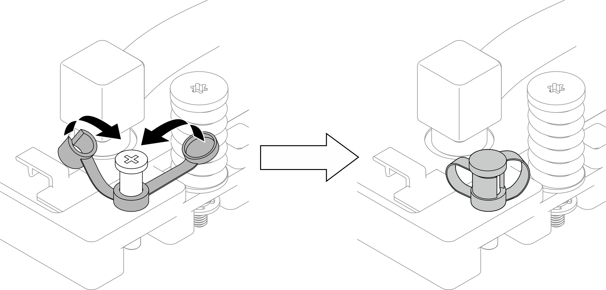
Figure 9. Séquence de serrage des vis de la plaque froide GPU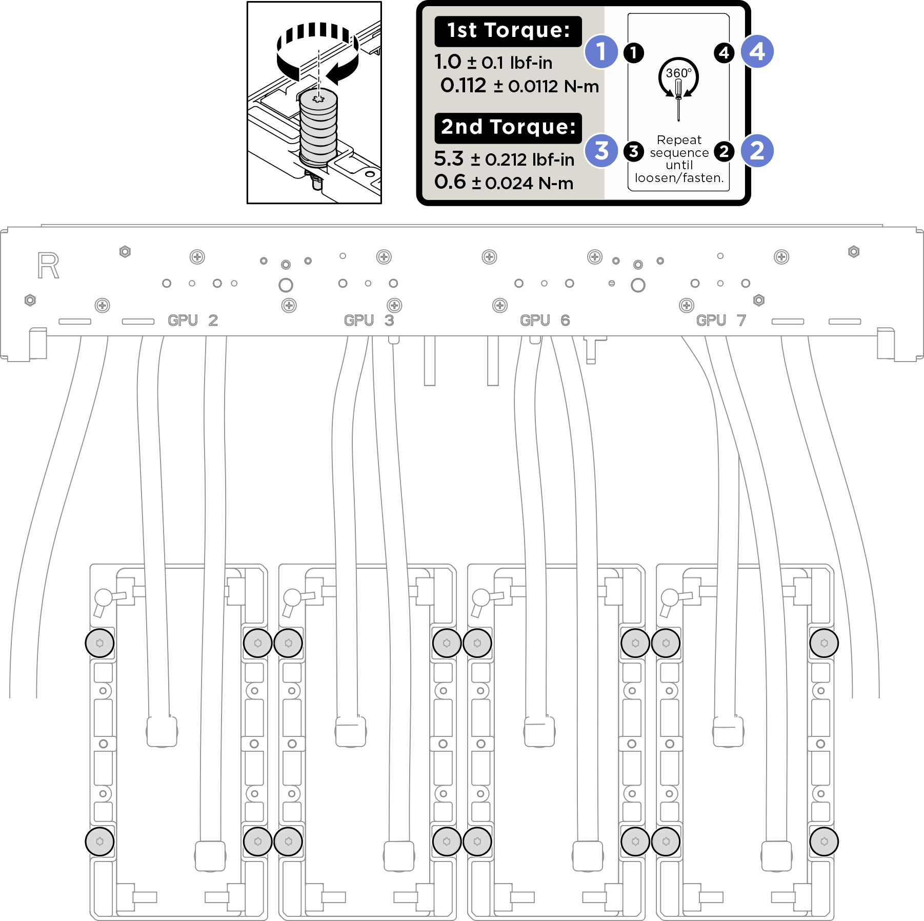
- L’illustration suivante présente l’emplacement du support de tuyaux.Figure 10. Emplacement du support de tuyaux
- Placez les tuyaux sur les guide-tuyaux et les supports de tuyaux.
- Placez les tuyaux et les câbles du module de plaque froide GPU B200 arrière sur les guide-tuyaux et fixez-les à l’aide de colliers de serrage. Voir Cheminement des câbles de la carte de contrôleur de ventilation et Cheminement des câbles du module de détecteur de fuite.RemarqueLorsque vous fixez des câbles sur le support de tuyaux, veillez à ne pas acheminer les câbles sur le dessus des tuyaux.Important
Avant l’installation, vérifiez les étiquettes de guidage sur les tuyaux et les supports de tuyaux.
Assurez-vous de garder le tuyau avant du module de plaque froide GPU à droite du tuyau arrière du module de plaque froide GPU.
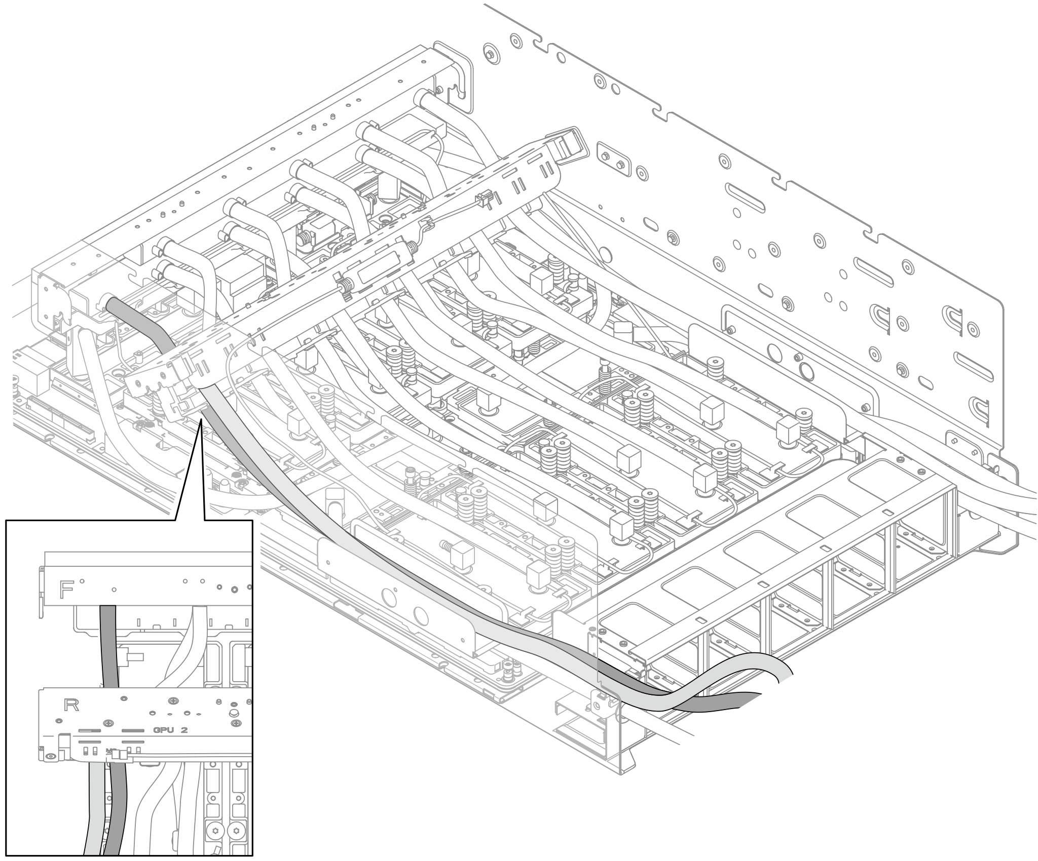
Assurez-vous de ne pas couvrir les joints avec les tuyaux.
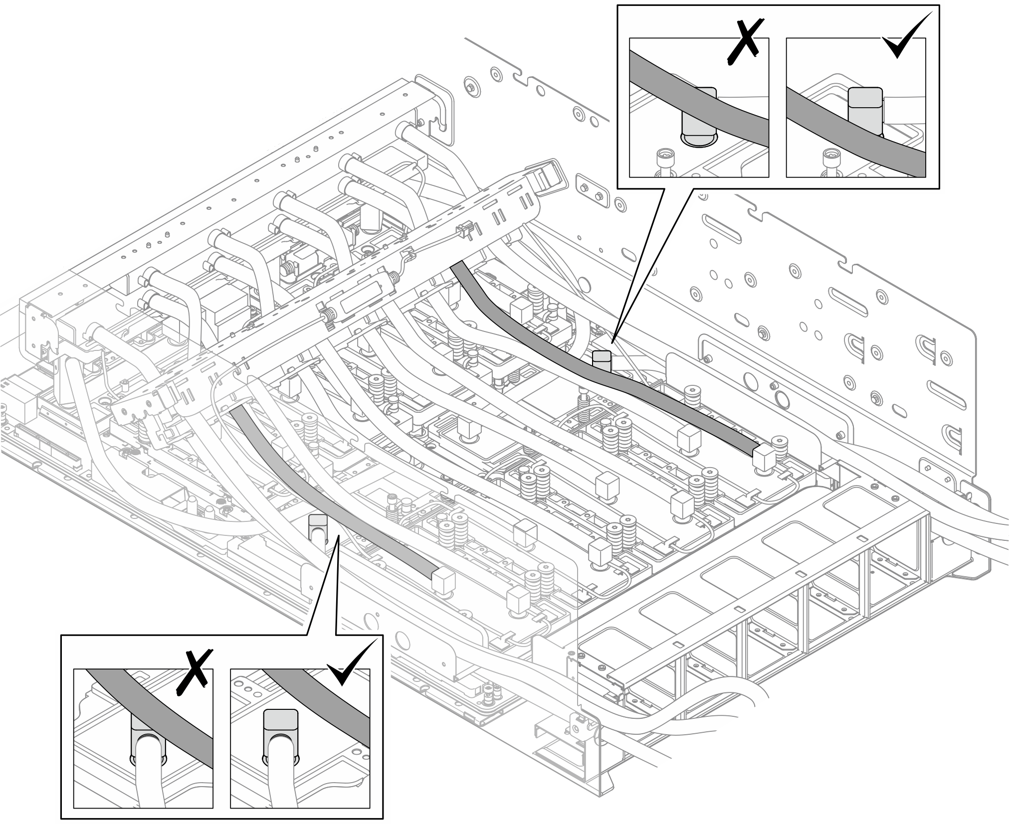
Figure 11. Fixation des tuyaux et des câbles à l’aide de colliers de serrage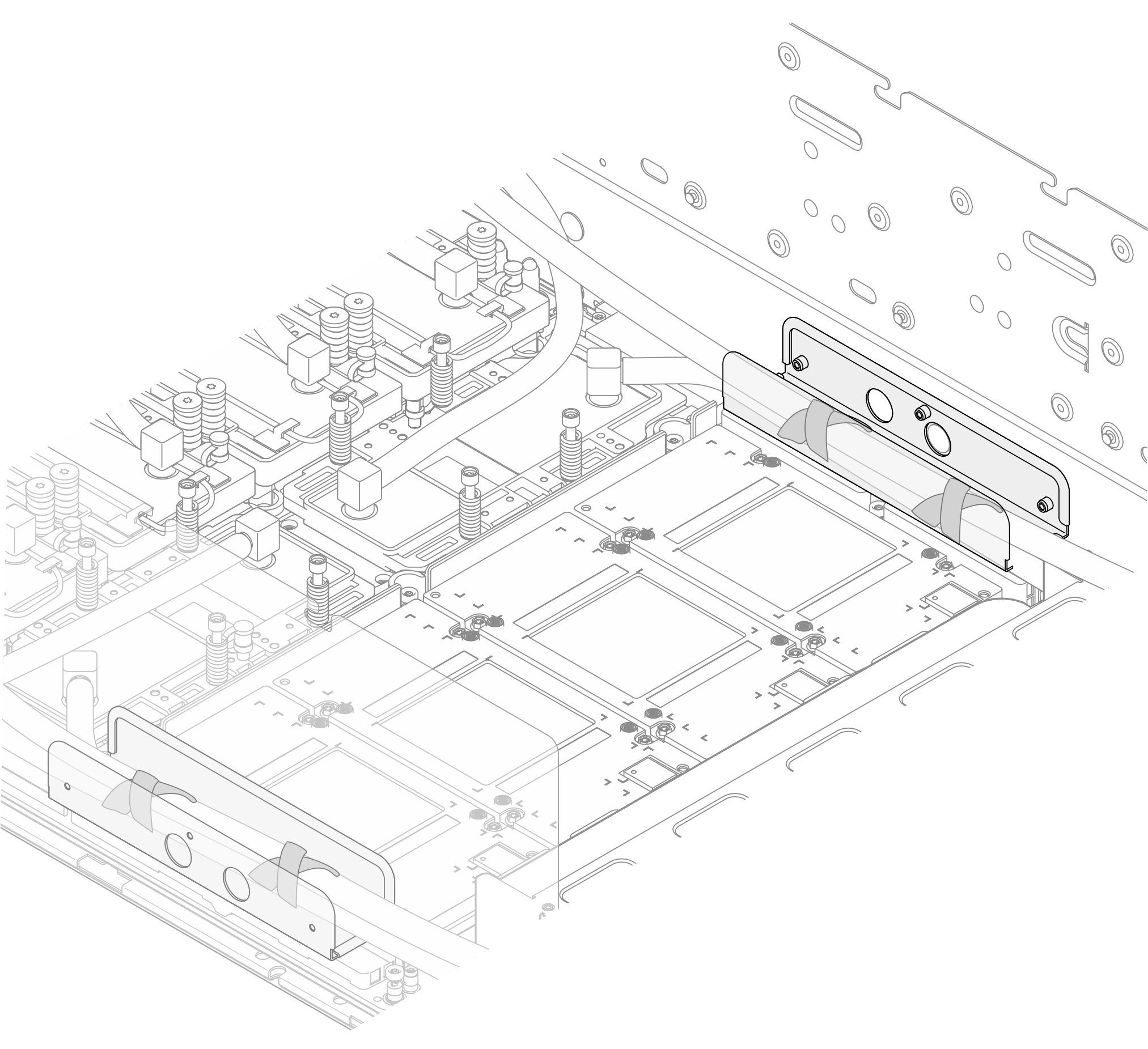
- Placez le tuyau du module de plaque froide GPU B200 arrière côté gauche sur le support de tuyau B (1) et le tuyau du module de plaque froide GPU B200 arrière côté droit sur le support de tuyau B (2). Assurez-vous que les étiquettes de guidage situées sur les tuyaux correspondent aux marquages des supports de tuyaux.Figure 12. Mise en place des tuyaux sur des supports de tuyaux
1 Support de tuyaux B (côté gauche) 2 Support de tuyaux B (côté droit)
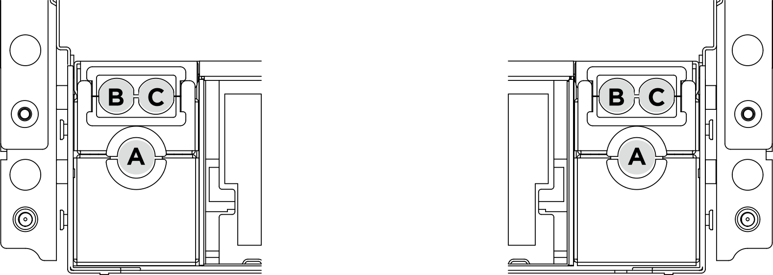
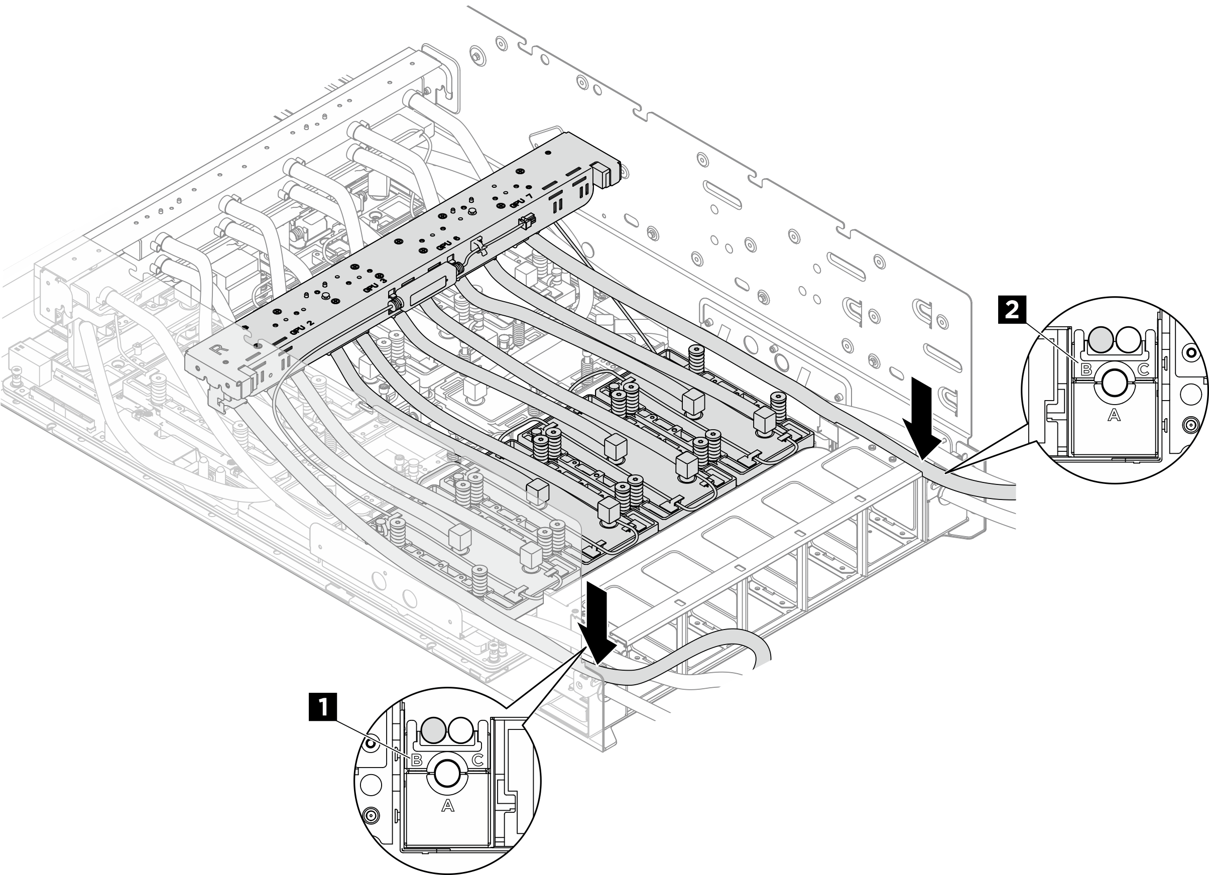
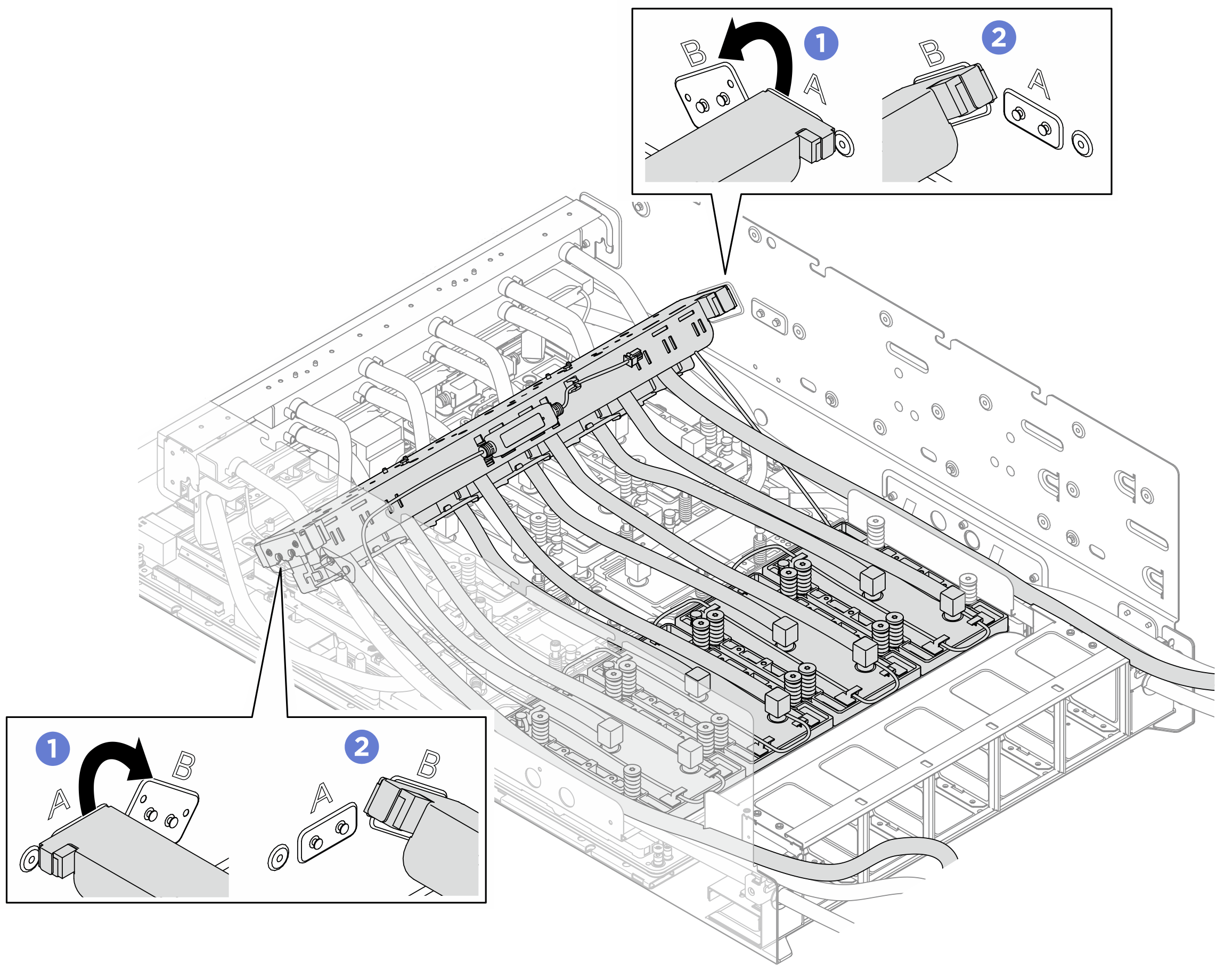
- Repositionnez le collecteur du module de plaque froide GPU B200 arrière, comme illustré.
- Dégagez le collecteur des broches de guidage marquées A ; déplacez ensuite le collecteur vers les broches de guidage marquées B.
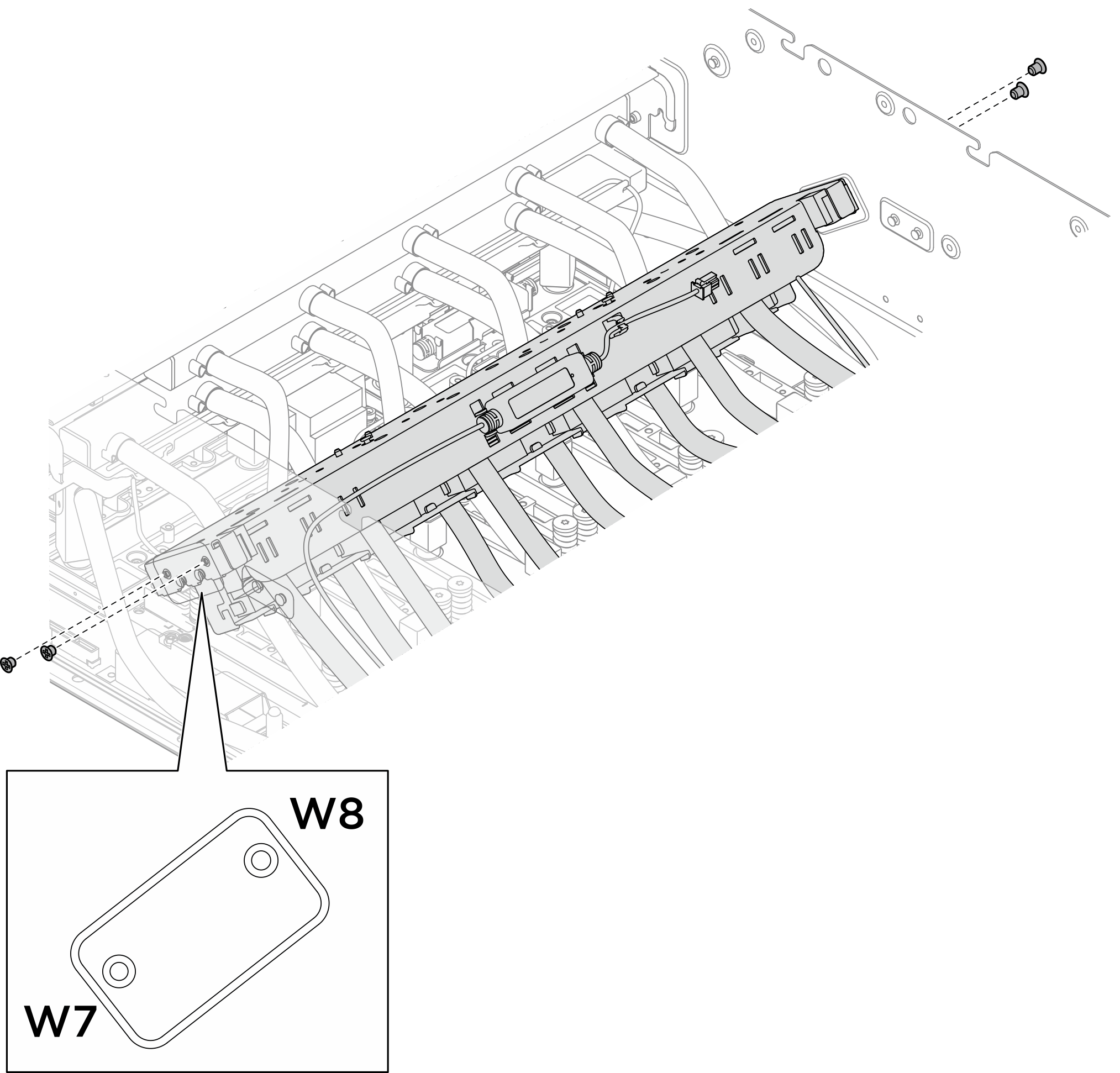
- Assurez-vous que les fentes de guidage sur le support du collecteur sont bien fixées aux broches de guidage marquées B.Figure 13. Repositionnement du collecteur du module de plaque froide GPU B200 arrière
- Serrez les quatre vis M3 (W7-W8) (PH2, 4 x M3, 0,5 newton-mètre, 4,3 pouces-livres) pour fixer le collecteur du module de plaque froide GPU B200 arrière au châssis.Figure 14. Installation du collecteur du module de plaque froide GPU B200 arrière
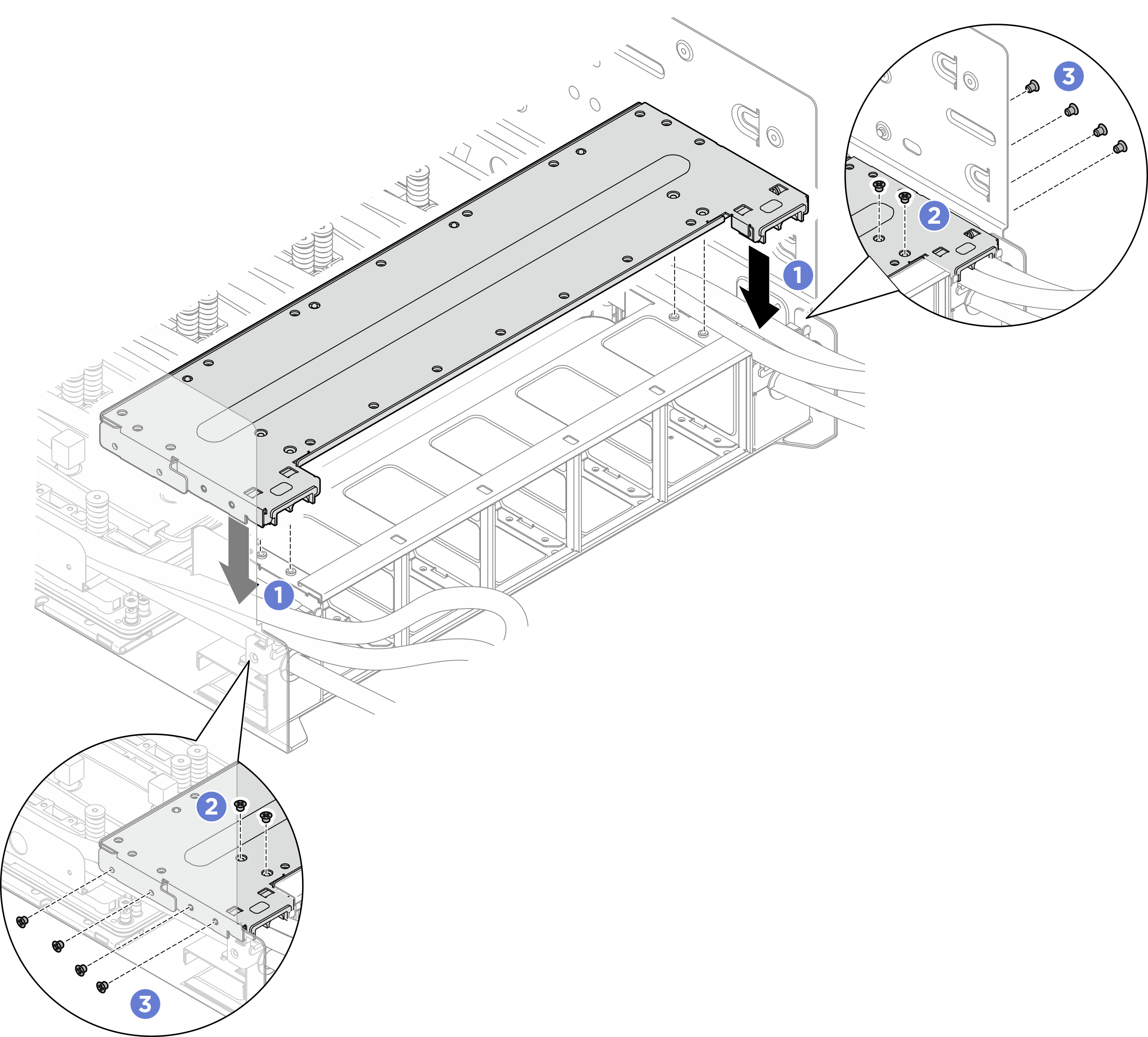
- Installez le support du boîtier de ventilation arrière.
- Alignez le support du boîtier de ventilation arrière sur les trous de vis correspondants ; installez ensuite le support du boîtier de ventilation arrière sur le dessus du support de tuyaux B/C, comme illustré.
- Serrez les quatre vis M3 (PH2, 4 x M3, 0,5 newton-mètre, 4,3 pouces-livres) pour fixer le support du boîtier de ventilation arrière au boîtier de ventilation.
- Serrez les huit vis M3 (PH2, 8 x M3, 0,5 newton-mètre, 4,3 pouces-livres) pour fixer le support du boîtier de ventilation arrière au châssis.Figure 15. Installation du support du boîtier de ventilation arrière
Après avoir terminé
- Reconnectez tous les câbles débranchés précédemment. Voir Cheminement interne des câbles.
- Réinstallez le complexe d’alimentation. Voir Installation du complexe d’alimentation.
- Réinstallez le complexe UC. Voir Installation du complexe UC.
- Réinstallez le boîtier de ventilation. Voir Installation du boîtier de ventilation (technicien qualifié uniquement).
- Réinstallez le carter supérieur arrière. Voir Installation du carter supérieur arrière.
- Réinstallez le carter supérieur avant. Voir Installation du carter supérieur avant.
- Terminez de remplacer les composants. Voir Fin du remplacement des composants.