System board LEDs
The following illustrations show the light-emitting diodes (LEDs) on the system board.
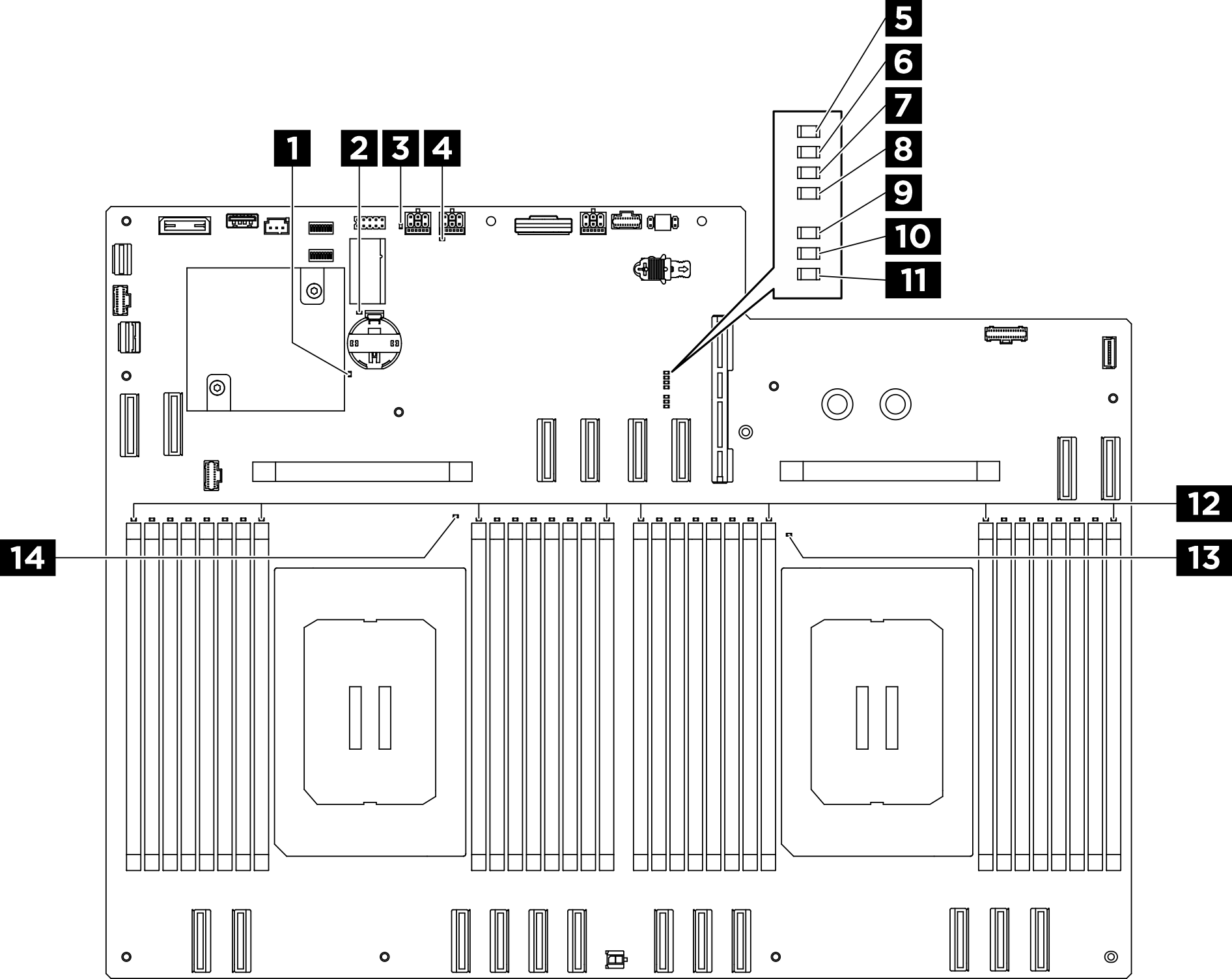
| LED | Description and actions |
|---|---|
| 1 ME heartbeat LED (green) |
|
| 2 CMOS battery error LED (yellow) | The system CMOS battery is not installed or is not working. |
| 3 M.2 slot 1 activity LED (green) |
|
| 4 M.2 slot 2 activity LED (green) |
|
| 5 P5V_AUX PGOOD LED (green) |
|
| 6 FPGA heartbeat LED (green) |
|
| 7 P12V PGOOD LED (green) | Indicates the system is DC on. |
| 8 System power LED (green) | The states of the power LED are as follows:
|
| 9 NMI error LED (amber) | Indicates that the system had an NMI (Non Maskable Interrupt). |
| 10 Processor mismatch LED (amber) | Indicates that processors are not matched. |
| 11 System-board-assembly error LED (yellow) | LED on: an error has occurred to the system board assembly. Complete the following steps:
|
| 12 DIMM error LEDs (1-32) (amber) |
|
| 13 Processor 1 error LED (amber) | LED on: an error has occurred to the processor the LED represents. Replace the processor. |
| 14 Processor 0 error LED (amber) | LED on: an error has occurred to the processor the LED represents. Replace the processor. |