Front view
This section contains information about the controls, LEDs, and connectors on the front of the server.
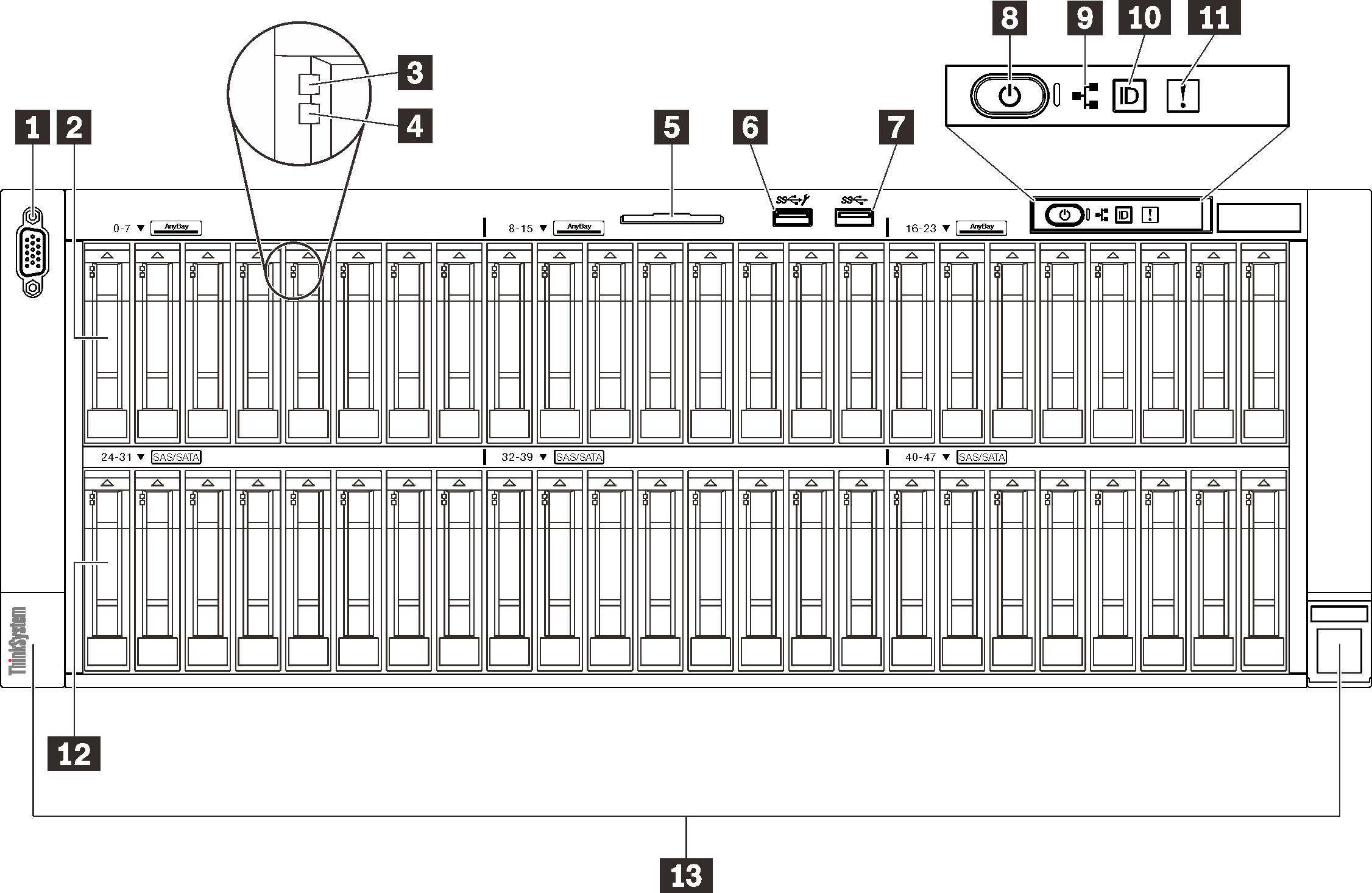
| 1 | VGA connector (optional) | 8 | Power button/LED (green) |
| 2 | 2.5-inch drive bays (bay 0 to 23) | 9 | Network activity LED (green) |
| 3 | Drive activity LED (green) | 10 | Identification button/LED (blue) |
| 4 | Drive status LED (yellow) | 11 | System error LED (yellow) |
| 5 | Pull-out information tab | 12 | 2.5-inch drive bays (bay 24 to 47) |
| 6 | USB 1 (USB 2.0 with Lenovo XClarity Controller management) | 13 | Rack release latches |
| 7 | USB 2 (USB 3.1) |
1 VGA connector (optional)
- When the optional front VGA connector is in use, the rear one will be disabled.
- The maximum video resolution is 1920 x 1200 at 60 Hz.
2/12 2.5-inch drive bays
Install 2.5-inch drives to these bays. See Install a 2.5-inch hot-swap drive for more details.3 Drive activity LED (green)
Each hot-swap drive comes with an activity LED. When this LED is flashing, it indicates that the drive is in use.
4 Drive status LED (yellow)
- The LED is lit: the drive has failed.
- The LED is flashing slowly (once per second): the drive is being rebuilt.
- The LED is flashing rapidly (three times per second): the drive is being identified.
5 Pull-out information tab
This tab contains network information such as MAC address and XCC network access label.
6/7 USB connectors
USB 1: USB 2.0 with Lenovo XClarity Controller management.
Connection to XClarity Controller is primarily intended for users with a mobile device running the XClarity Controller mobile application. When a mobile device is connected to this USB port, an Ethernet over USB connection is established between the mobile application running on the device and the XClarity Controller.
Select Network in BMC Configuration to view or modify settings.
Four types of settings are available:
Host only mode
In this mode, the USB port is always solely connected to the server.
BMC only mode
In this mode, the USB port is always solely connected to XClarity Controller.
Shared mode: owned by BMC
In this mode, connection to the USB port is shared by the server and XClarity Controller, while the port is switched to XClarity Controller.
Shared mode: owned by host
In this mode, connection to the USB port is shared by the server and XClarity Controller, while the port is switched to the server.
USB 2: USB 3.1.
9 Network activity LED (green)
When this LED is lit, it indicates that the server is transmitting to or receiving signals from the Ethernet LAN.
10 Identification button/LED (blue)
Use this blue LED to visually locate the server among other servers. This LED is also used as a presence detection button. You can use Lenovo XClarity Administrator to light this LED remotely.
11 System error LED (yellow)
When this yellow LED is lit, it indicates that a system error has occurred. This LED can be controlled by the XCC. Information provided from the LCD display of the LCD diagnostics panel could also help isolate an error.
13 Rack release latches
Press on the latch on both sides to disengage the server from the rack and slide it out.