System-board connectors for cable routing
The following illustrations show the internal connectors on the system board that are used for internal cable routing.
Figure 1. System-board connectors
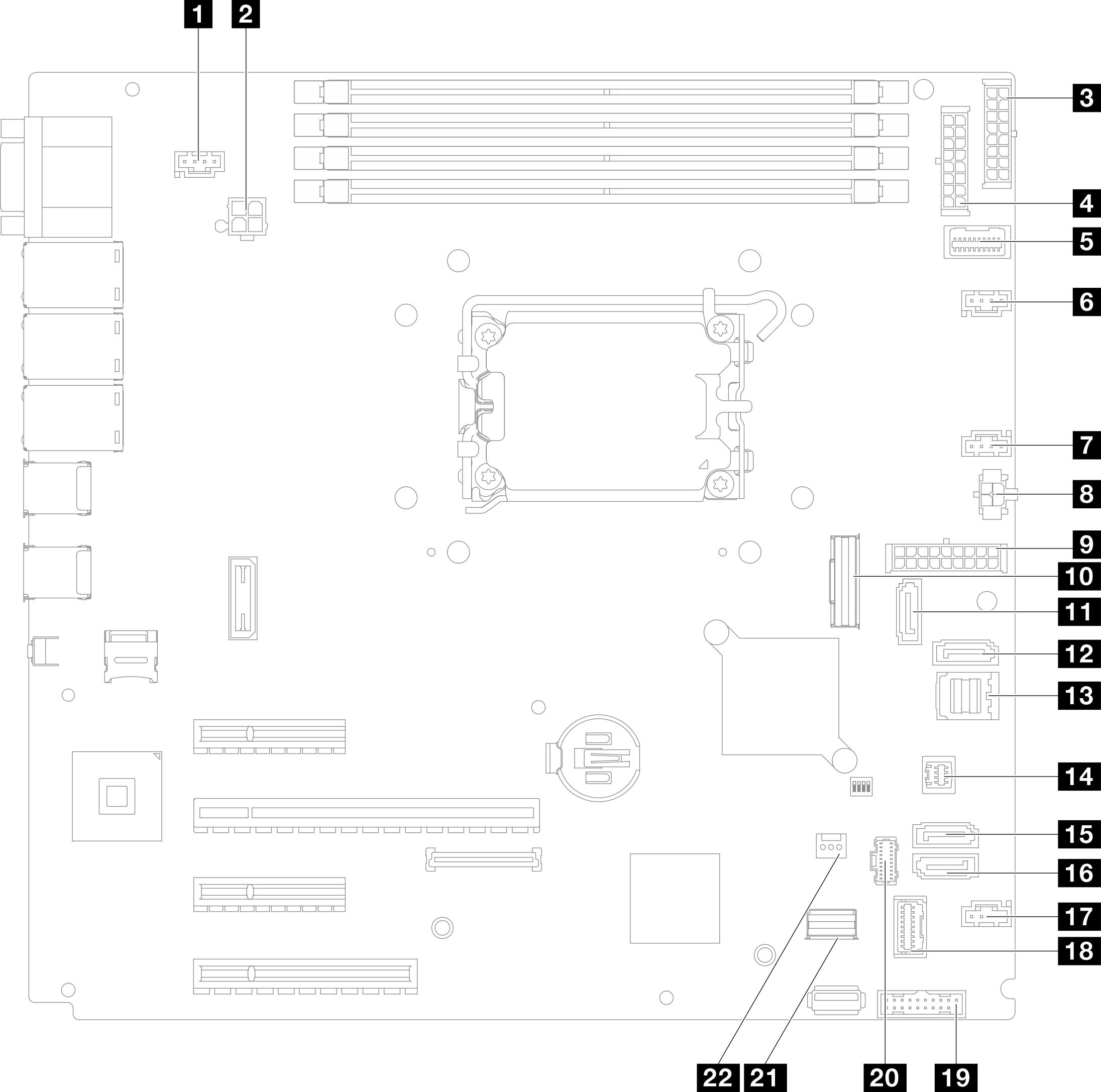
| 1 SYS_FAN3 connector | 12 SATA 7 |
| 2 Processor power connector | 13 SATA 0–3 |
| 3 BP2 power connector | 14 SGPIO1 connector |
| 4 BP1 power connector | 15 SATA 5 |
| 5 Power distribution board side band connector | 16 SATA 4 |
| 6 Fan1 connector | 17 Fan4 connector |
| 7 Fan2 connector | 18 Front I/O module connector |
| 8 Optical drive power connector | 19 Front USB 3.0/2.0 header |
| 9 System power connector | 20 M.2 power connector |
| 10 Slimline x8 connector | 21 M.2 signal connector |
| 11 SATA 6 | 22 Intrusion switch connector |
Give documentation feedback