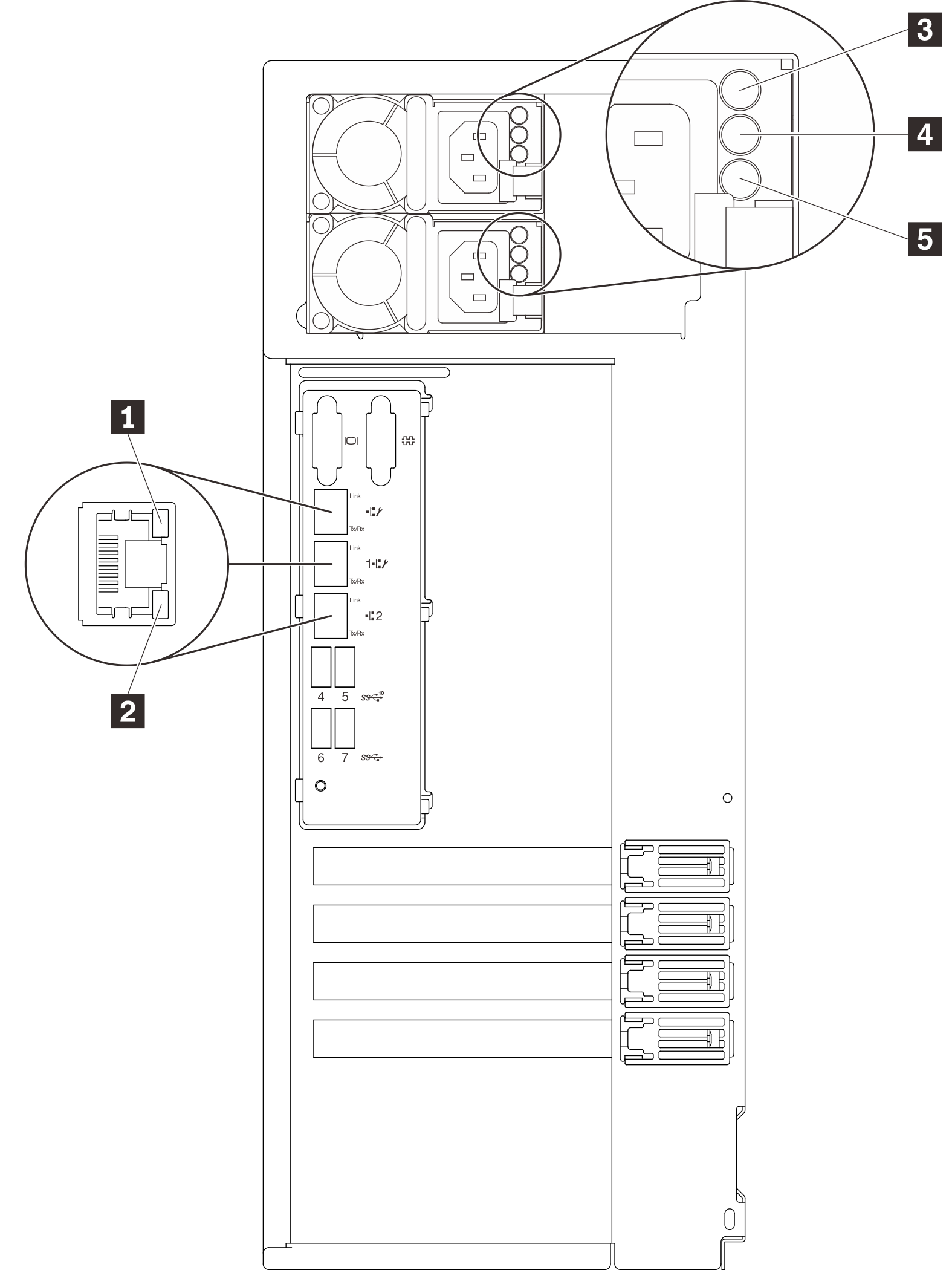
The illustration in this section shows the LEDs on the rear the server.
Figure 1. Rear view LEDs of the server Table 1. LEDs on the rear of the server| Callout | Callout |
|---|
| 1 Ethernet link LED (green) | 4 Power output LED (green) |
| 2 Ethernet activity LED (green) | 5 Power supply error LED (yellow) |
| 3 Power input LED (green) | |
1 2 Ethernet status LEDs
Each network connector has two status LEDs.
| Ethernet status LED | Color | Status | Description |
|---|
| 1 Ethernet link LED | Green | On | Network link is established. |
| None | Off | Network link is disconnected. |
| 2 Ethernet activity LED | Green | Blinking | Network link is connected and active. |
| None | Off | The server is disconnected from a LAN. |
3 Power input LED4 Power output LED5 Power supply error LED
Each hot-swap power supply has three status LEDs.
| LED | Description |
|---|
| 3 Power input LED | |
| 4 Power output LED | Green: The server is on and the power supply is working normally. Blinking green: The power supply is in zero-output mode (standby). When the server power load is low, one of the installed power supplies enters into the standby state while the other one delivers entire load. When the power load increases, the standby power supply will switch to active state to provide sufficient power to the server. To disable zero-output mode, start the Setup utility, go to and select Disable. If you disable zero-output mode, both power supplies will be in the active state. Off: The server is powered off, or the power supply is not working properly. If the server is powered on but the power output LED is off, replace the power supply.
|
| 5 Power supply error LED | Off: The power supply is working normally. Yellow: The power supply has failed. To resolve the issue, replace the power supply.
|