Front view
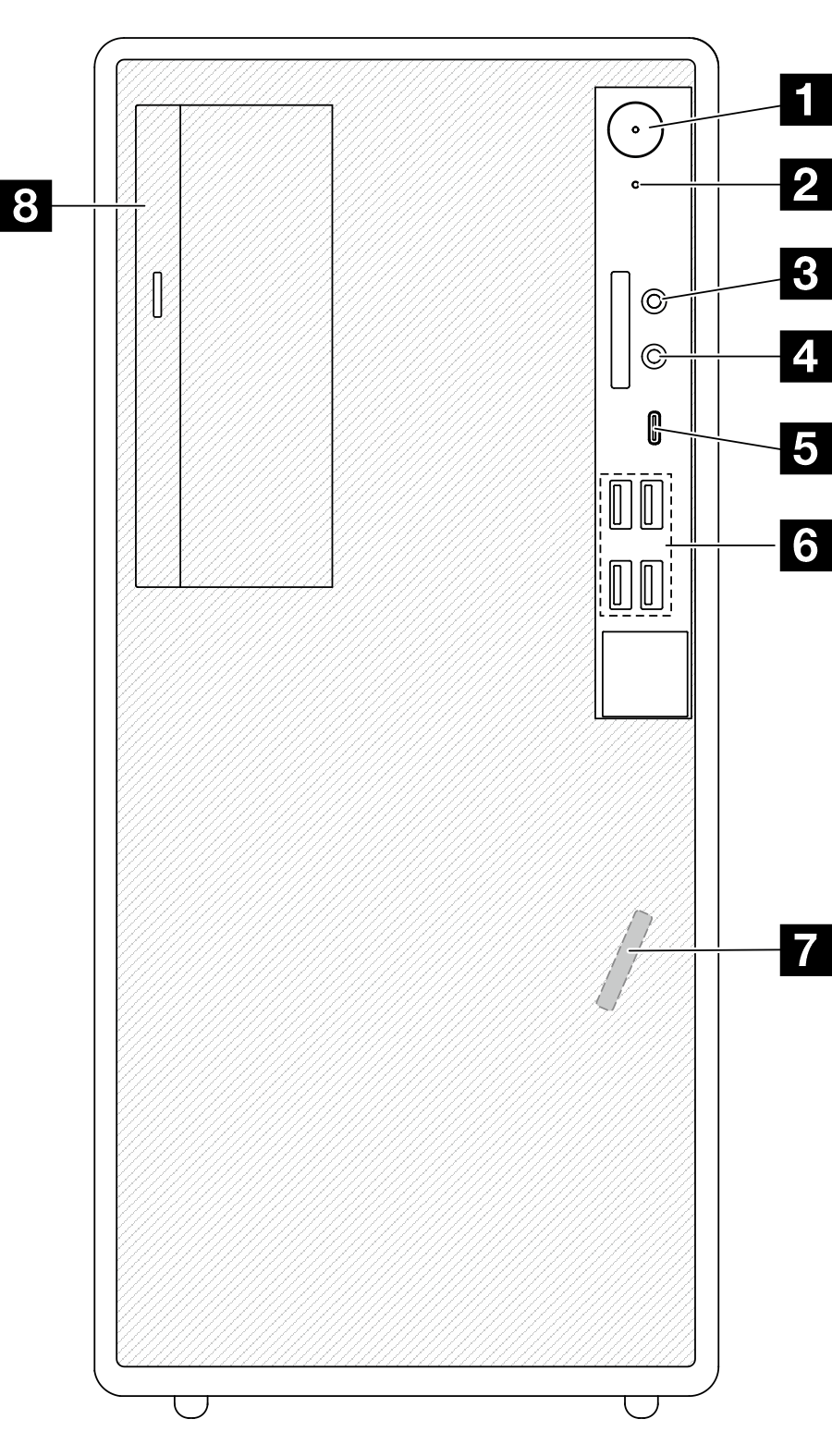
This section contains information about the controls, LEDs, and connectors on the front of the server.
Figure 1. Front view


| 1 Power button/LED (white) | 2 Drive activity LED (white) |
| 3 Mic-in connector (Windows Client OS only) | 4 Headset connector (Windows Client OS only) |
| 5 USB Type-C 3.2 Gen 1 (5 Gbps) connector | 6 USB Type-A 3.2 Gen 1 (5 Gbps) connectors (x4) |
| 7 Front thermal sensor | 8 Optical-drive bay (optional) |
2 Drive activity LED (white)
This LED indicates the activity of the drives.
Note
The drive activity LED only indicates the activities of drives that are connected to the SATA ports on the system board.
| Status | Color | Description |
| Blinking | White | The drives are active. |
| Off | None | The drives are not active. |
3 Mic-in connector
Plug in a microphone to this connector.
Note
This connector is only supported by Windows Client OS.
4 Headset connector
Plug in a headset with microphone to this connector. A standard headphone or microphone can also be plugged into the connector.
Note
This connector is only supported by Windows Client OS.
5 USB Type-C 3.2 Gen 1 (5 Gbps) connector
The connector is available for a Type-C compatible device that requires USB 2.0 or 3.0 connection, such as a keyboard, a mouse, or a USB flash drive.
6 USB Type-A 3.2 Gen 1 (5 Gbps) connectors (x4)
These connectors are available for Type-A compatible devices that require USB 2.0 or 3.0 connection, such as a keyboard, a mouse, or a USB flash drive.
7 Front thermal sensor
The thermal sensor works by converting temperature variations into electrical signals. It can measure the temperature of a system or space.
8 Optical drive bay
Depending on the model, the server might come with an optical drive installed in this drive bay. See Optical drive and drive cage replacement.
Give documentation feedback