Rear view
The rear of the server provides access to several connectors and components.
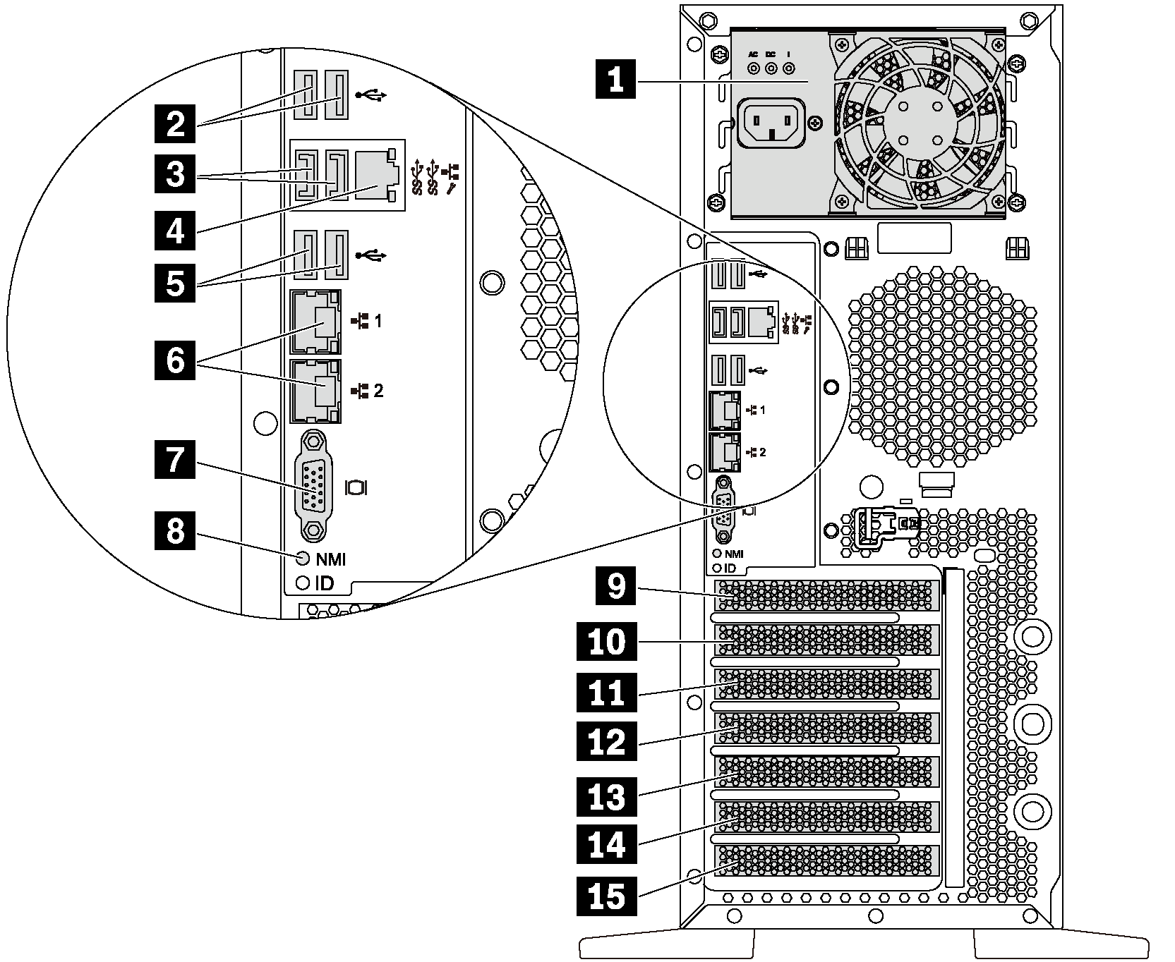
Rear view of server models with a fixed power supply
| Callout | Callout |
|---|---|
| 1 Fixed power supply | 2 USB 2.0 connectors (2) |
| 3 USB 3.0 connectors (2) | 4 XClarity Controller network connector |
| 5 USB 2.0 connectors (2) | 6 Ethernet connectors (2) |
| 7 VGA connector | 8 NMI button |
| 9 Serial-port-module slot | 10 PCIe slot 1 |
| 11 PCIe slot 2 | 12 PCIe slot 3 |
| 13 PCIe slot 4 | 14 PCIe slot 5 |
| 15 PCIe slot 6 |
1 Fixed power supply
Used to connect the power cord.
2 3 5 USB connectors
Used to attach a device that requires a USB 2.0 or 3.0 connection, such as a keyboard, a mouse, or a USB flash drive.
4 XClarity Controller network connector
Used to attach an Ethernet cable to manage the system using XClarity Controller.
6 Ethernet connectors
Used to attach an Ethernet cable for a LAN. Each Ethernet connector has two status LEDs to help you identify the Ethernet connectivity and activity. For more information, see Rear view LEDs.
7 VGA connector
Used to attach a VGA-compatible video device, such as a VGA monitor.
8 NMI button
Press this button to force a nonmaskable interrupt (NMI) to the processor. By this way, you can blue screen the server and take a memory dump. You might have to use a pen or the end of a straightened paper clip to press the button.
9 Serial-port-module slot
Used to install a serial port module. The serial port module is available on some models. For instructions on how to install the serial port module, see Install the serial port module.
10 11 12 13 14 15 PCIe slots
Your server has six PCIe slots on the system board for you to install appropriate PCIe adapters. For information about the PCIe slots, see Specifications.
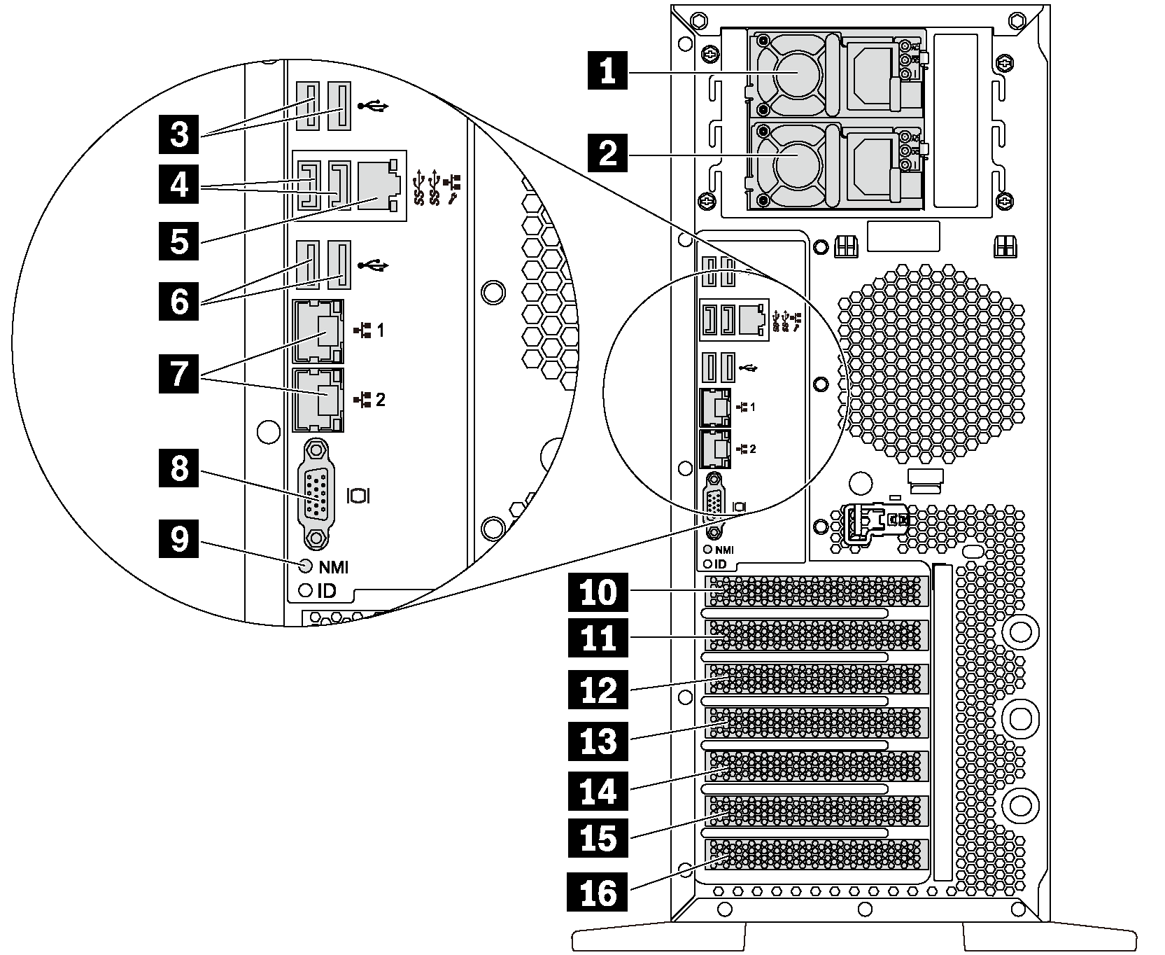
Rear view of server models with two hot-swap power supplies
| Callout | Callout |
|---|---|
| 1 Power supply 1 | 2 Power supply 2 (available on some models or available as an option) |
| 3 USB 2.0 connectors (2) | 4 USB 3.0 connectors (2) |
| 5 XClarity Controller network connector | 6 USB 2.0 connectors (2) |
| 7 Ethernet connectors (2) | 8 VGA connector |
| 9 NMI button | 10 Serial-port-module slot |
| 11 PCIe slot 1 | 12 PCIe slot 2 |
| 13 PCIe slot 3 | 14 PCIe slot 4 |
| 15 PCIe slot 5 | 16 PCIe slot 6 |
1 Power supply 1
2 Power supply 2 (available on some models or available as an option)
The hot-swap redundant power supplies help you avoid significant interruption to the operation of the system when a power supply fails. You can purchase a power supply option from Lenovo and install the power supply to provide power redundancy without turning off the server.
On each power supply, there are three status LEDs near the power cord connector. For information about the status LEDs, see Rear view LEDs.
3 4 6 USB connectors
Used to attach a device that requires a USB 2.0 or 3.0 connection, such as a keyboard, a mouse, or a USB flash drive.
5 XClarity Controller network connector
Used to attach an Ethernet cable to manage the system using XClarity Controller.
7 Ethernet connectors
Used to attach an Ethernet cable for a LAN. Each Ethernet connector has two status LEDs to help you identify the Ethernet connectivity and activity. For more information, see Rear view LEDs.
8 VGA connector
Used to attach a VGA-compatible video device, such as a VGA monitor.
9 NMI button
Press this button to force a nonmaskable interrupt (NMI) to the processor. By this way, you can blue screen the server and take a memory dump. You might have to use a pen or the end of a straightened paper clip to press the button.
10 Serial-port-module slot
Used to install a serial port module. The serial port module is available on some models. For instructions on how to install the serial port module, see Install the serial port module.
11 12 13 14 15 16 PCIe slots
Your server has six PCIe slots on the system board for you to install appropriate PCIe adapters. For information about the PCIe slots, see Specifications.