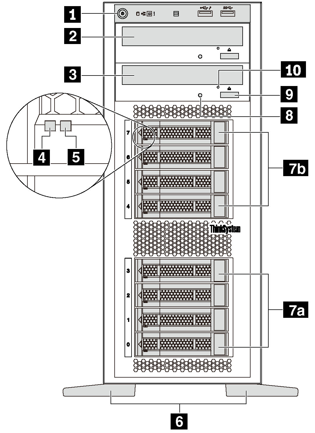
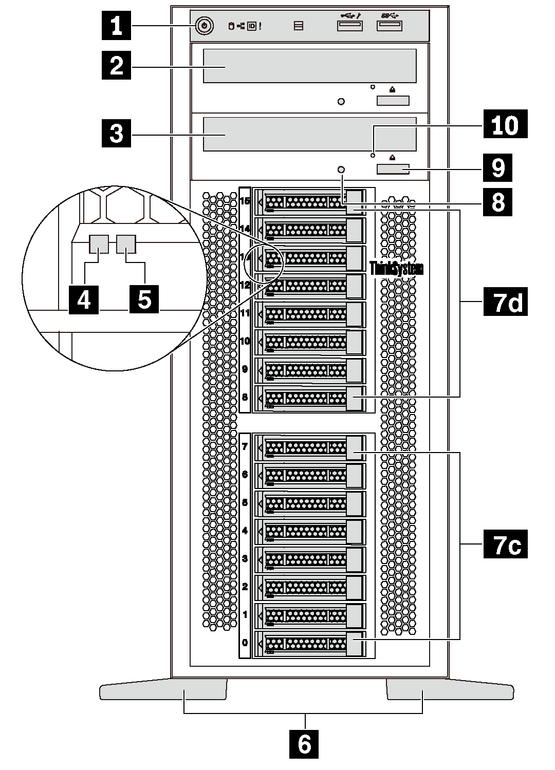
Front view
The front view of the server varies by model.
| Front view of server models with two optical drive bays and eight 3.5-inch-drive bays | Front view of server models with two optical drive bays and sixteen 2.5-inch-drive bays |
|---|---|
 |  |
| Callout | Callout |
|---|---|
| 1 Front panel | 2 Optical-drive bay 2 |
| 3 Optical-drive bay 1 | 4 Drive activity LED (green) |
| 5 Drive status LED (yellow) | 6 Foot stands |
| 7a 3.5-inch drive bays 0–3 | 7b 3.5-inch drive bays 4–7 |
| 7c 2.5-inch drive bays 0–7 | 7d 2.5-inch drive bays 8–15 |
| 8 Optical-drive status LED | 9 Optical-drive eject/close button |
| 10 Optical-drive manual-eject hole |
1 Front panel
For information about the controls, connectors, and status LEDs on the front panel, see Front panel.
2 Optical-drive bay 2
The 5.25-inch optical-drive bay 2 is for a secondary optical drive or a tape drive. Some models have a secondary optical drive or a tape drive installed.
3 Optical-drive bay 1
Depending on the model, your server might come with an optical drive installed in the 5.25-inch optical-drive bay 1.
4 Drive activity LED
5 Drive status LED
| Drive LED | Status | Description |
|---|---|---|
| 4 Drive activity LED (left) | Solid green | The drive is powered but not active. |
| Blinking green | The drive is active. | |
| 5 Drive status LED (right) | Solid yellow | The drive has an error. |
| Blinking yellow (blinking slowly, about one flash per second) | The drive is being rebuilt. | |
| Blinking yellow (blinking rapidly, about four flashes per second) | The RAID adapter is locating the drive. |
6 Foot stands
For tower-form-factor models, your server comes with four foot stands. To help the server stand steadily, ensure that you install the foot stands correctly as shown. See Install the foot stands.
7a 7b 7c 7d Drive bays
Four 3.5-inch-drive bays
Eight 3.5-inch-drive bays
Eight 2.5-inch-drive bays
Sixteen 2.5-inch-drive bays
8 Optical-drive status LED
The optical-drive status LED is blinking in green when the optical drive is working or in the POST process.
9 Optical-drive eject/close button
Press this button to eject or close the optical drive when the server power is on.
10 Optical-drive manual-eject hole
Insert a straightened paper clip into the optical-drive manual-eject hole to eject the disc tray when the eject/close button does not work.
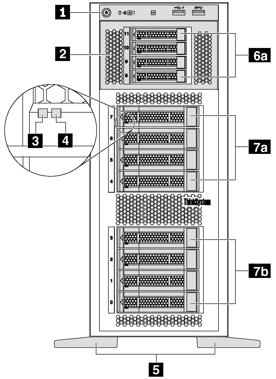
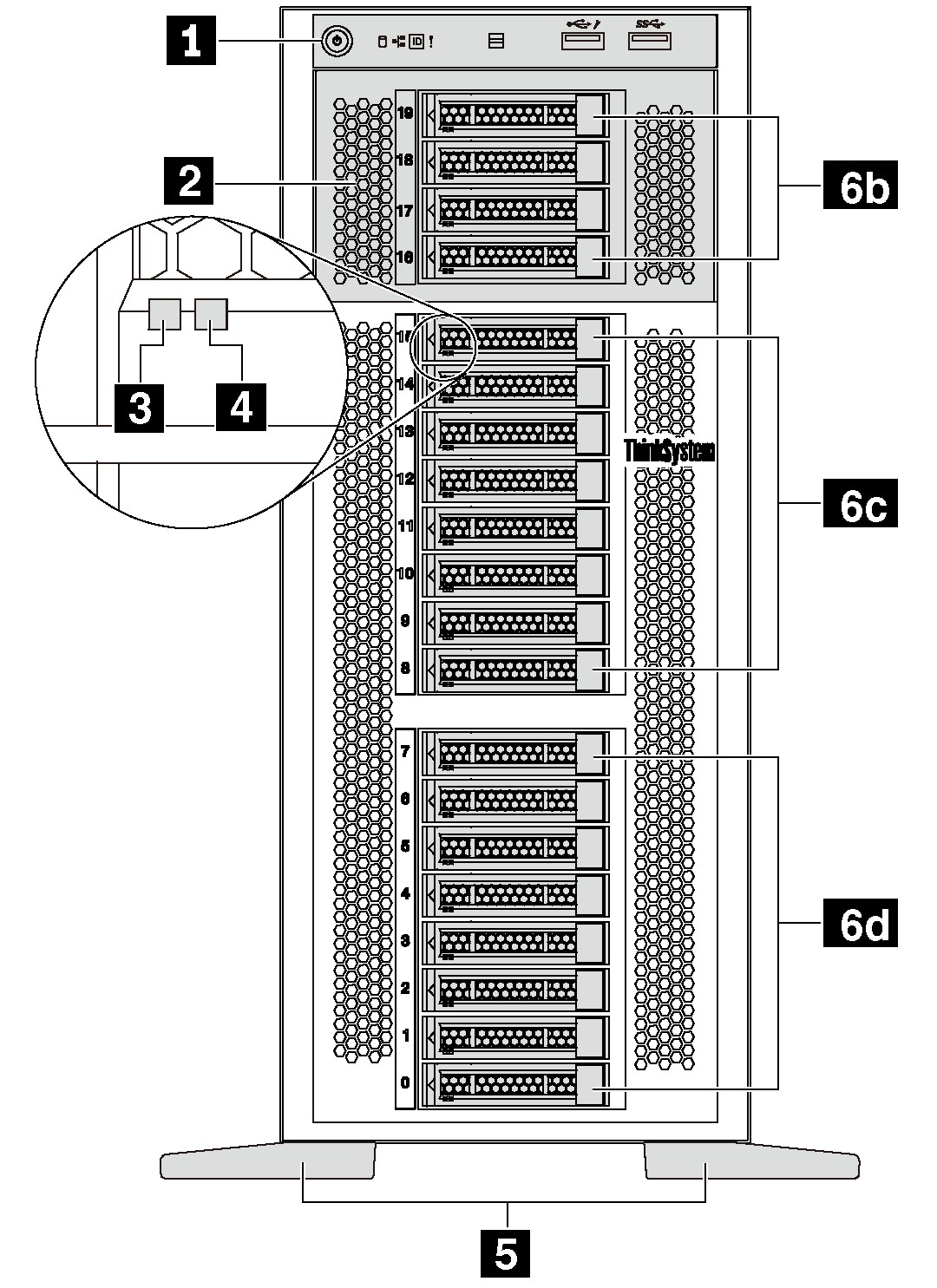
| Front view of server models with eight 3.5-inch-drive bays and four 2.5-inch-drive bays | Front view of server models with twenty 2.5-inch-drive bays |
|---|---|
 |  |
| Callout | Callout |
|---|---|
| 1 Front panel | 2 Expansion drive cage |
| 3 Drive activity LED (green) | 4 Drive status LED (yellow) |
| 5 Foot stands | 6a 2.5-inch drive bays 8–11 |
| 6b 2.5-inch drive bays 16–19 | 6c 2.5-inch drive bays 8–15 |
| 6d 2.5-inch drive bays 0–7 | 7a 3.5-inch drive bays 4–7 |
| 7b 3.5-inch drive bays 0–3 |
1 Front panel
For information about the controls, connectors, and status LEDs on the front panel, see Front panel.
2 Expansion drive cage
For some server models, your server comes with an expansion drive cage. You can install up to four 2.5-inch SAS/SATA drives to the cage.
3 Drive activity LED
4 Drive status LED
| Drive LED | Status | Description |
|---|---|---|
| 3 Drive activity LED (left) | Solid green | The drive is powered but not active. |
| Blinking green | The drive is active. | |
| 4 Drive status LED (right) | Solid yellow | The drive has an error. |
| Blinking yellow (blinking slowly, about one flash per second) | The drive is being rebuilt. | |
| Blinking yellow (blinking rapidly, about four flashes per second) | The RAID controller is locating the drive. |
5 Foot stands
For tower-form-factor models, your server comes with four foot stands. To help the server stand steadily, ensure that you install the foot stands correctly as shown. See Install the foot stands.
6a 6b 6c 6d 7a 7b Drive bays