System board jumpers
The following illustration shows the location of the jumpers on the server.
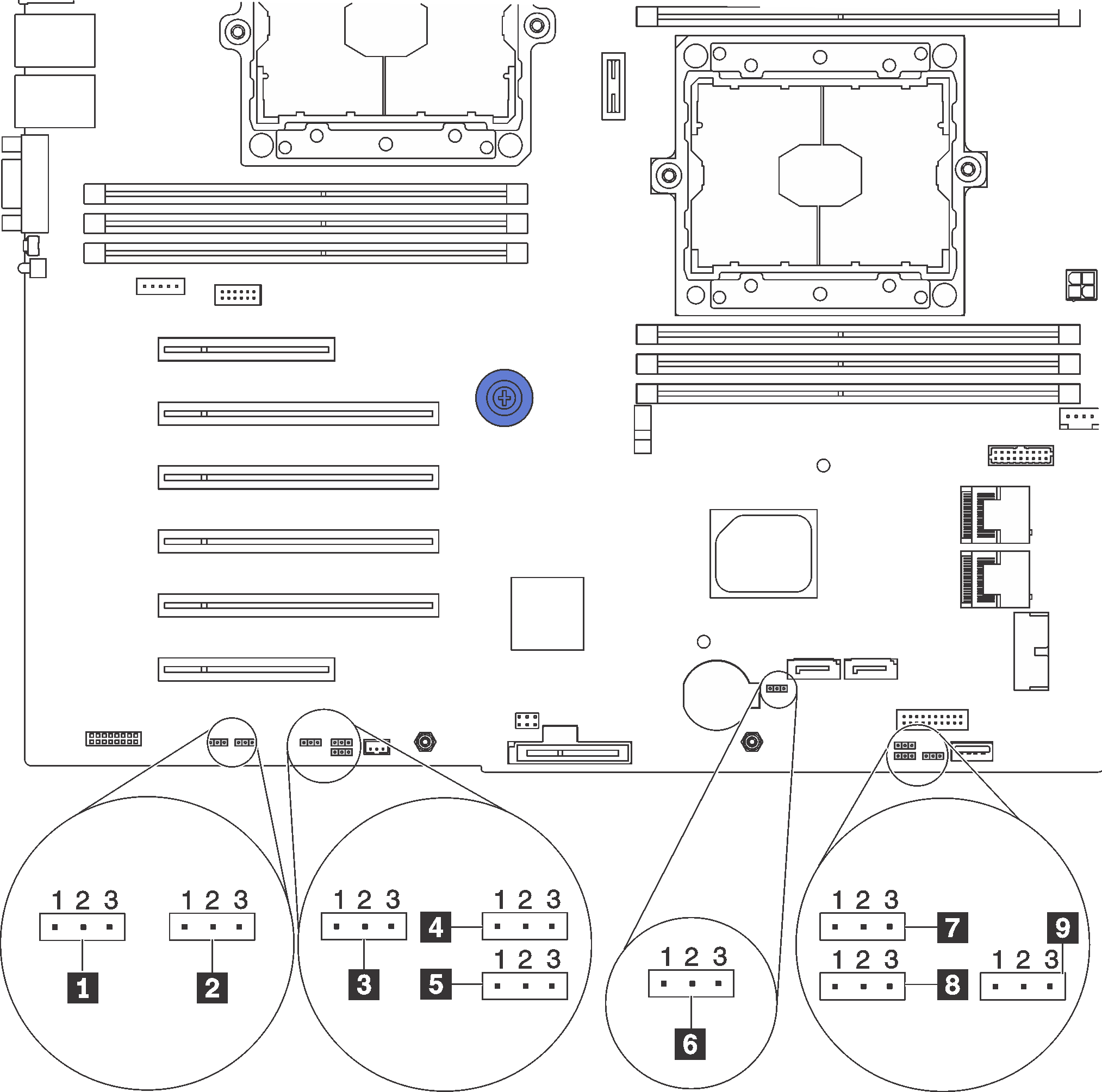
Figure 1. System board jumpers
| Jumper name | Jumper number | Jumper setting |
|---|---|---|
| 1 Force XCC update jumper | JP16 |
|
| 2 Force XCC reset jumper | JP19 |
|
| 3 TPM/TCM physical presence jumper | JP23 |
|
| 4 Power permission | JP72 |
|
| 5 Boot backup XClarity Controller | JP71 |
|
| 6 Clear CMOS jumper | JP76 |
|
| 7 ME recovery | JP59 |
|
| 8 ME firmware security override | JP38 |
|
| 9 Override power-on password jumper | JP61 |
|
Important
- Before you move the jumpers, turn off the server. Then, disconnect all power cords and external cables. Do not open your server or attempt any repair before reading and understanding the following information:
- Any system-board switch or jumper block that is not shown in the illustrations in this document are reserved.
Give documentation feedback